



Diagram 3-4. Engine control unit, mass air flow sensor, electromagnetic valves of hydraulic engine mounts
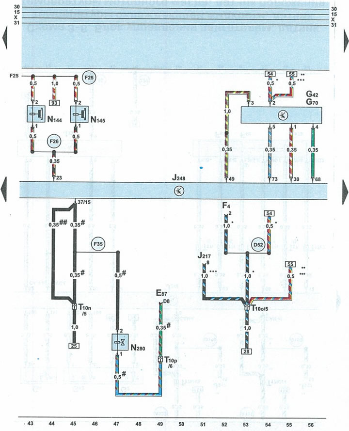
| E87 | heater/air conditioner switch block |
| F | reverse light switch |
| G42 | intake air temperature sensor |
| G70 | mass air flow sensor |
| J217 | automatic transmission control unit |
| J248 | engine control unit/fuel system |
| N144 | left engine mount solenoid valve |
| N145 | right engine mount solenoid valve |
| N₂80 | air conditioner compressor pressure reducing valve |
| T10n | 10-pin orange plug near the fuse/relay box under the fairing |
| T10o | 10-pin brown connector on fuse/relay box under cowl |
| T10p | 10-pin black plug near the fuse and relay box under the fairing |
| D52 | positive potential wire terminal 15a in the engine compartment wiring harness |
| F25 | connection 1 in the power supply wiring harness |
| F26 | connection 2 in the power supply wiring harness |
| F35 | connection 4 in the power supply wiring harness |
| * | cars with manual transmission |
| ** | cars with automatic transmission 01V |
| *** | cars with automatic transmission Multitronic 01J |
| # | except Allroad vehicles |
| ## | allroad vehicles only |
(The article is a reprint of material from: «AUDIMANUAL.ru»)