
Repair Chevrolet Repair Toyota Repair Honda Repair AvtoVAZ Repair Mercedes-Benz Repair BMW Repair Opel
Home  |  Contacts  |  Sitemap  |    
English Русский
Български
Беларускі
Український
Српски
Hrvatski
Română
Polski
Slovenský
Magyar
AudiManual.ru


  • AUDI 80
  • AUDI 100
  • AUDI A3
  • AUDI A4
  • AUDI A6
  • AUDI A8
  • AUDI Q
  • OTHER
  • ARTICLES
C5 Allroad (1999-2005) C5 (1997-2004) C4 (1994-1997)

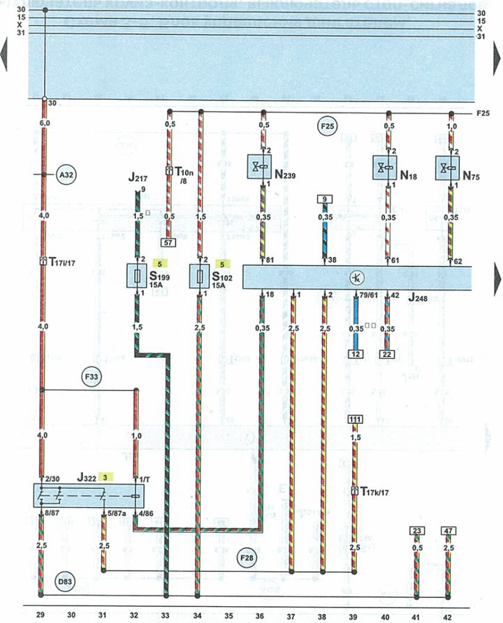
Schematic 3-3. Engine/fuel system control unit, fuel system relay (Audi A6 C5)
  • Home
  • Audi A6
  • C5 Allroad (1999-2005)
  • Electrical equipment
  • Schemes (diesel engine 2.5 l)
  • Schematic 3-3. Engine/fuel system control unit, fuel system relay
            0

Schematic 3-3. Engine/fuel system control unit, fuel system relay


Schematic 3-3. Engine/fuel system control unit, fuel system relay


J217automatic transmission control unit
J248engine control unit/fuel system
J322power supply system relay
N18eGR valve
N75boost air pressure reducing valve
N₂39intake throttle actuator valve
S102engine control unit fuse
S199fuse 1 x 15A in the fuse and relay box
T10n10-pin orange plug near the fuse/relay box under the fairing
T17i17-pin white plug on fuse/relay box under cowl
T17k17-pin red connector on the fuse/relay box under the fairing
A32positive potential wire terminal 30 in the instrument panel wiring harness
D83wire terminal 87 in the engine compartment wiring harness
F25connection 1 in the power supply wiring harness
F28connection 3 in the power supply wiring harness
F33positive potential wire of terminal 30 in the power supply wiring harness
*cars with automatic transmission
**except Allroad vehicles
The article was checked by auto expert Alexey Ivanov
This article is available at russian, bulgarian, belarusian, ukrainian, serbian, croatian, romanian, polish, slovak, hungarian

Share information:
Previous articles
Audi A6 C5 Allroad: Schemes (diesel engine 2.5 l)
Next articles

Schematic 3-2. Preheating unit, glow plugs, heating relay
Scheme 3-1. Battery, starter, generator, immobilizer relay
Diagram 3-4. Engine control unit, mass air flow sensor...
Diagram 3-5. Engine control unit, cruise control switch, brake…
Diagram 3-6. Engine control unit, coolant temperature sensor...
Diagram 3-7. Engine control unit, tachometer sensor, sensor in…


Similar articles on other Audi car models:
Electrical diagram of the control unit of the fuel system of the… Audi 80 B4 (1991-1996)
Mono-Motronic injection system control unit, fuel pump relay,… Audi 100 C4 (1990-1994, petrol)
Control unit for Simos, fuel pump relay, injectors, ignition… Audi A3 Type 8L (1996-2003)
Bleeding the fuel system (1.8L petrol engine) Audi A4 B6 (2000-2006)
General information about the ignition and fuel injection system Audi A8 D2 (1994-2002)
Comfort system control unit, heated rear window and its relay,… Audi Q7 Typ 4L (2005-2015, diesel)
Removal and installation the central control unit of the comfort… Audi A2 (1999-2005)
Link to this page in different formats


Visitor comments

No comments yet


How much will 50 + 27 =


A6(C5 AR, 1999-2005) 
  • General information
  • User manual
  • Maintenance
  • Troubleshooting
  • Power unit
  • V6 petrol engines
  • V8 petrol engines
  • Diesel engines
  • Cooling and heating system
  • Injection system (gasoline)
  • Fuel system (diesel)
  • Supply system
  • Exhaust system
  • Ignition system
  • Transmission
  • Clutch
  • Mechanical gearbox
  • Automatic gearbox
  • Chassis
  • Brake system
  • Car suspension
  • Steering
  • Body
  • Body elements
  • Doors, locks and windows
  • Electrical equipment
  • Equipment and devices
  • Power devices
  • Electrical circuits
  • Schemes (petrol engine 2.7 l)
  • Schemes (petrol engine 4.2 l)
  • Schemes (diesel engine 2.5 l)
 
A6(C5, 1997-2004) 
  • General information
  • User manual
  • Maintenance
  • Power unit
  • Engine repair
  • Cooling system
  • Fuel system
  • Engine management
  • Fuel system (diesel)
  • Exhaust system
  • Transmission
  • Clutch
  • Car gearbox
  • Chassis
  • Front suspension
  • Rear suspension
  • Steering
  • Wheels and tires
  • Brake system
  • Body
  • Exterior
  • Interior
  • Electrical equipment
  • Air conditioner
  • Equipment and devices
  • Electrical circuits
 
A6(C4, 1994-1997) 
  • General information
  • User manual
  • Maintenance (gasoline)
  • Maintenance (Diesel)
  • Gasoline engines
  • 4 cylinder engines
  • 5 cylinder engines
  • 6 cylinder engines
  • Diesel engines
  • 4 cylinder engines
  • 5 cylinder engines
  • Engine repair
  • Removal and reassembly
  • Cooling system
  • Single point injection system
  • Multipoint injection system
  • MPI/MPFI injection system
  • Fuel system (diesel)
  • Exhaust system
  • Ignition system
  • Transmission
  • Clutch
  • Manual transmission
  • Automatic transmission
  • Drive shafts
  • Chassis
  • Brake system
  • Front suspension
  • Rear suspension
  • Steering
  • Body
  • Exterior (external elements)
  • Interior (internal elements)
  • Electrical equipment
  • Power devices
  • Lighting and appliances
  • Electrical circuits
 
AudiManual.ru © 2017-2026 · Mobile version · Feedback · Sitemap: EN BG BY UA RS HR RO PL SK HU · Site search · News and articles
80 B2 · 80 B3 petrol · 80 B3 · 80 B4 · 100 C3 diesel · 100 C3 petrol · 100 C3 · 100 C4 petrol · 100 C4 · A3 Type 8L · A4 B5 petrol · A4 B5 · A4 B6 petrol · A4 B6 · A4 B7 · A4 B8 · A6 C4 · A6 C5 · A6 C5 Allroad · A8 D2 · Q5 Type 8R · Q7 Typ 4L · Audi A2 ·
This site uses cookies 🍪. Click the button to accept this fact.