
Diagram 3-5. Engine control unit, cruise control switch, brake light switch
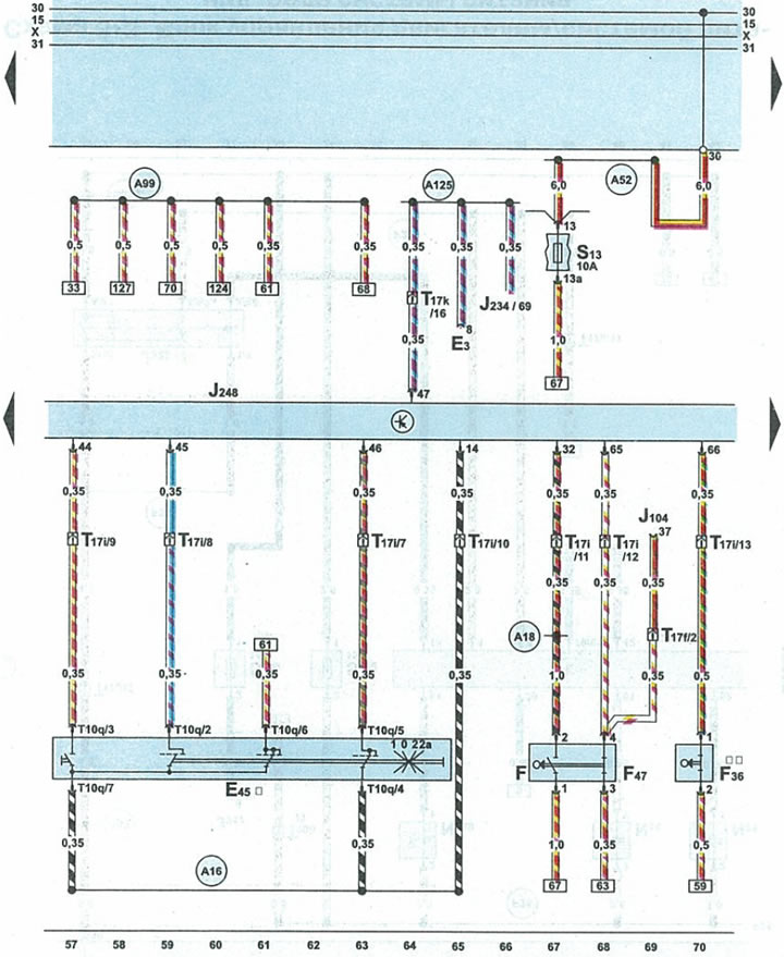
| EZ | hazard warning light switch |
| E45 | cruise control switch |
| F | brake light switch |
| F36 | clutch pedal sensor |
| F47 | cruise control switch sensor on brake pedal |
| J104 | ABS control unit with EDS |
| J220 | engine control unit |
| J234 | airbag control unit |
| J248 | engine control unit |
| S13 | fuse |
| T10q | 10-pin black plug for cruise control switch |
| T17f | 17-pin black plug on relay box under glove compartment on driver's side |
| T17i | 17-pin white plug on fuse/relay box under cowl |
| T17k | 17-pin red connector on the fuse/relay box under the fairing |
| A16 | cruise control wire in instrument cluster wiring harness |
| A18 | terminal 54 wire in instrument panel wiring harness |
| A52 | wire 2 positive potential terminal 30 in the instrument panel wiring harness |
| A99 | wire 1 terminal 87 in the instrument panel wiring harness |
| A125 | collision signal transmission wire (crash signal) in the instrument panel wiring harness |
| * | cars with cruise control |
| ** | cars with manual transmission |
(This publication is borrowed from the resource AUDIMANUAL)