
Anti-lock and slip systems are integrated into the electronic stabilization system. ESP additionally measures yaw rate, lateral acceleration, brake pressure, and steering angle. Based on the steering angle and vehicle speed, the system determines the direction in which the vehicle driver intends to travel and compares it with the actual direction of travel. If these factors do not agree, when the car begins to drift or skid, the stabilization system automatically brakes a certain wheel.
In the event of a malfunction, the electronic control system is automatically switched off, and the control lamps in the instrument cluster light up. In this case, the braking system operates normally.
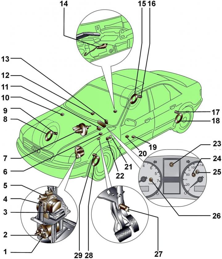
Pic. 15–1. Location on the vehicle of the elements of the anti-lock braking system and electronic stabilization system (ABS/ ESP): 1 - hydraulic pump; 2 - pressure sensor in the brake system; 3 - pump relay J105 for the Bosch 5.3 system; 4 - electromagnetic valve relay J106 for the Bosch 5.3 system; 5 - hydraulic block N55 with control unit J104; 6 - control unit J104 for the Bosch 5.0 system; 7 - brake fluid level sensor - F34; 8 – a rotor of the forward right gauge ABS; 9 - front right ABS sensor - G45; 10 - control unit J104 (with ESP); 11 - angle sensor G85 (with ESP); 12 – switch for TCS/ESP-E132 systems; 13 – rotation angle sensor G85; 14 - switch of the control lamp of the state of the parking brake F9; 15 - the rotor of the rear right ABS sensor; 16 - rear right ABS sensor - G44; 17 - rear left ABS sensor - G46; 18 – a rotor of the back left gauge ABS; 19 - side acceleration sensor G200; 20 - status sensor G202; 21 - pump relay J105 for the Bosch 5.3 system; 22 - electromagnetic relay J106 for the Bosch 5.3 system; 23 - control lamp K118; 24 - control lamp ABS - K47; 25 - control lamp of the parking brake status - K14; 26 - control lamp TCS / ESP - K86; 27 - stoplight switch F; 28 - the rotor of the front left ABS sensor; 29 - front left ABS sensor - G47
The location of the ABS and ESP elements on the vehicle and the front axle is shown in fig. 15–1 and 15–2.
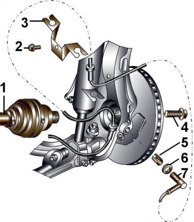
Pic. 15–2. Location of ABS/ESP elements on the front axle: 1 - drive shaft with ABS sensor rotor (if the ABS sensor rotor is damaged, the outer drive shaft joint must be replaced); 2 - bolt, 10 Nm; 3 - bracket for attaching the ABS sensor wire with a sealing ring; 4 - bolt; 5 - clamping sleeve; 6 - seal; 7 - ABS sensor
Visitor comments