
Table of contents: Accelerator pedal position sensor ↓ Coolant temperature sensor ↓ Crankshaft speed sensor ↓ Shut-off valve ↓ Engine starting system valve ↓ Pressure regulating valve (1Z and… ↓ Incoming air temperature sensor (aVR… ↓ Air flow sensor (except AAS engines) ↓ Electronic control unit ↓ System relay ↓ Clutch and brake pedal switches ↓ Fuel temperature sensor ↓
Accelerator pedal position sensor
Removal
1. Remove the trim panel.
2. Disconnect the cable, return spring and remove the pedal from the bracket.
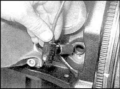
3. Loosen the mounting bolts and remove the sensor.
Installation
Installation is carried out in the reverse order of removal.
Coolant temperature sensor
Removal
1. Drain some of the coolant from the engine.
2. Disconnect the connection connector and unscrew the sensor.
Installation
Installation is carried out in the reverse order of removal.
Crankshaft speed sensor
Removal
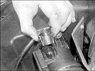
1. Disconnect the connection connector.
2. Loosen the mounting screws and remove the sensor from the cylinder block (aAT engine).
Installation
Installation is carried out in the reverse order of removal.
Shut-off valve
Removal
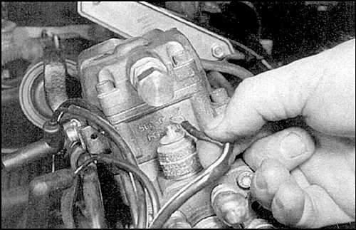
1. Unscrew the fastening nut and disconnect the wire.
2. Unscrew the valve and remove the sealing ring.
Installation
Installation is carried out in the reverse order of removal.
Engine starting system valve
Removal
1. Loosen the mounting screw and remove the valve from the injection pump.
2. Remove the sealing rings and filter. Disconnect the connection connector.
Installation
Installation is carried out in the reverse order of removal.
Pressure regulating valve (1Z and AHU engines)
Removal
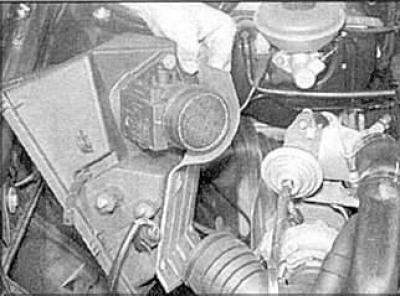
1. Disconnect the air ducts that interfere with removal.
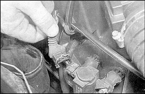
2. Disconnect the connection connector.
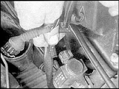
3. Disconnect the vacuum hoses, marking them before removing.
4. Unscrew the mounting nuts and remove the valve.
Installation
Installation is carried out in the reverse order of removal.
Incoming air temperature sensor (aVR engine)
Removal
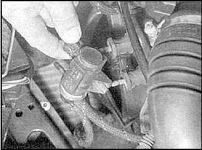
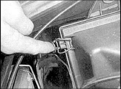
1. Disconnect the connection connector.
2. Remove the retaining clip and remove the sensor.
Installation
Installation is carried out in the reverse order of removal.
Air flow sensor (except AAS engines)
Removal
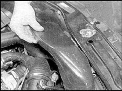
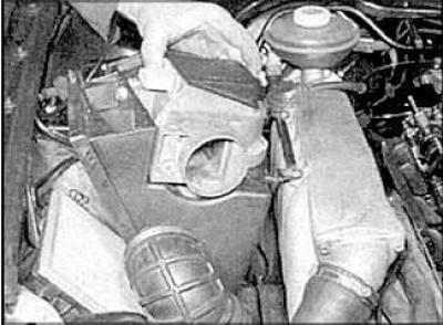
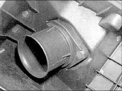
1. Remove the plastic cover from the inlet pipe and the intermediate pipe.
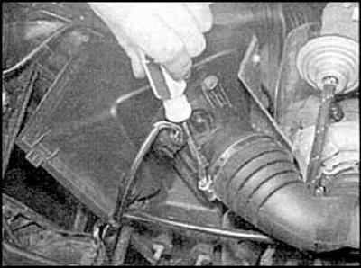
2. Disconnect the air hose from the air flow sensor.
3. Disconnect the air hose from the sensor.
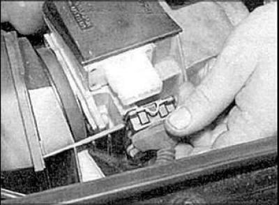
4. Release the cover retaining clips.
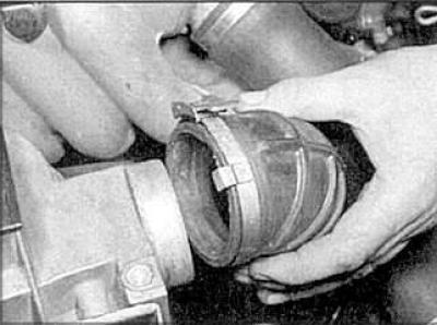
5. Disconnect the connection connector and remove the cover and air flow sensor.
6. Disconnect the connection connector and remove the cover and sensor (aAT engine).
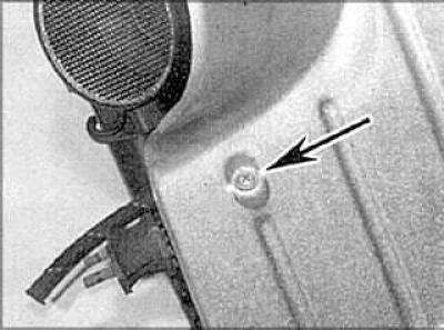
7. Remove the sensor shield.
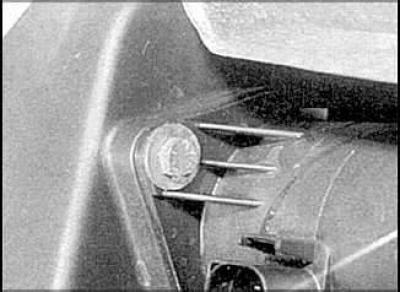
8. Remove the air flow sensor mounting bolts.
Installation
Installation is carried out in the reverse order of removal.
Electronic control unit
Removal
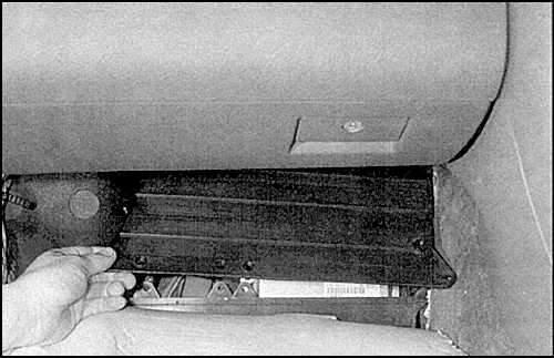
1. Remove the trim panel and the electronic control unit cover.
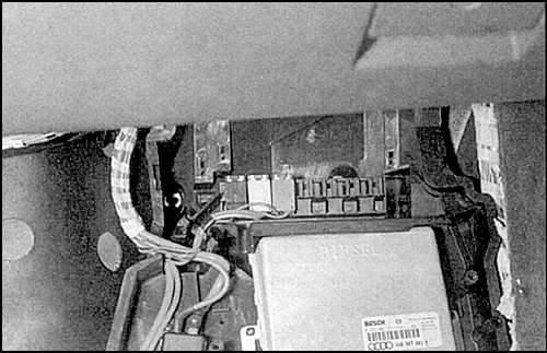
2. Loosen the mounting bolts to gain access to the electronic control unit and remove it, disconnect the connection connectors.
Installation
Installation is carried out in the reverse order of removal.
System relay
Removal
1. Remove the trim panel.
2. Loosen the mounting screw, remove the cover and take out the relay.
Installation
Installation is carried out in the reverse order of removal.
Clutch and brake pedal switches
Look subsection 9.1.5 and subsection 10.15.
Fuel temperature sensor
Removal
1. Remove the injection pump cover.
2. Loosen the mounting screws and remove the sensor.
Installation
Installation is carried out in the reverse order of removal.
(The article was copied from the website: «AUDIMANUAL.RU»)