Repair Chevrolet Repair Toyota Repair Honda Repair AvtoVAZ Repair Mercedes-Benz Repair BMW Repair Opel
Home  |  Contacts  |  Sitemap  |    
English Русский
Български
Беларускі
Український
Српски
Hrvatski
Română
Polski
Slovenský
Magyar
AudiManual.ru


  • AUDI 80
  • AUDI 100
  • AUDI A3
  • AUDI A4
  • AUDI A6
  • AUDI A8
  • AUDI Q
  • OTHER
  • ARTICLES
C5 Allroad (1999-2005) C5 (1997-2004) C4 (1994-1997)

Removal and installation switches (Audi A6 C4)

  • Home
  • Audi A6
  • C4 (1994-1997)
  • Electrical equipment
  • Lighting and appliances
  • Removal and installation switches
            0
Table of contents: Ignition/Steering Column Lock Switch ↓ Combination switches on the steering… ↓ Switches on the instrument panel ↓ Rear view mirror regulator ↓ Driver's door window switches ↓ Central lock switch on the driver's… ↓ Rear door window switch ↓ Passenger door window switch ↓ Electric sunroof switch ↓ Interior light switch ↓ Brake light switch ↓ Switch on the handbrake lever ↓ Front seat power switch ↓ Front Seat/Rear View Mirror… ↓ Rear Seat Heater Switches ↓ Trunk light switch ↓

Ignition/Steering Column Lock Switch


Look subsection 11.6.3.

Combination switches on the steering column


Removal


1. Remove the steering wheel.
1. Remove the steering wheel.


2. Remove the mounting clamp and lever.
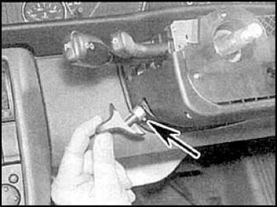
2. Remove the mounting clamp and lever.


3. Unscrew the screw (indicated by the arrow) and remove the lever.
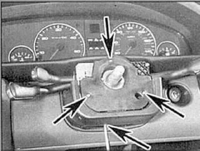


3. Unscrew the screw (indicated by the arrow) and remove the lever.


4. On Audi A6 models, remove the mounting screws and remove the cover.
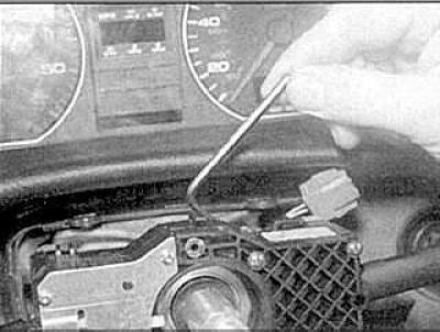
4. On Audi A6 models, remove the mounting screws and remove the cover.


5. Loosen the mounting screw.
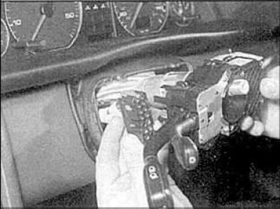
5. Loosen the mounting screw.


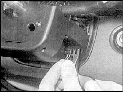
6. Disconnect the connection connectors and remove the switches.
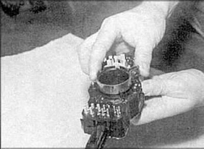
6. Disconnect the connection connectors and remove the switches.


7. To remove the switch components, remove the clamp.
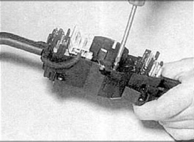


7. To remove the switch components, remove the clamp.


8. Loosen the mounting screws.

Installation


Installation is carried out in the reverse order of removal.

Switches on the instrument panel


Removal
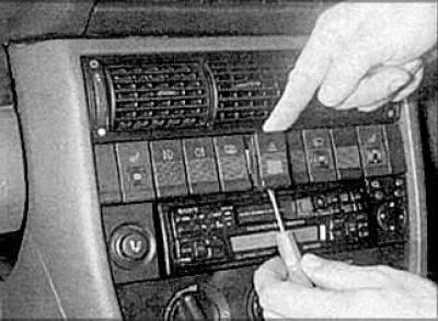


Removal


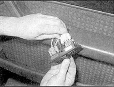
1. Hook the switch and remove it, disconnecting the connection connector.

2. If necessary, remove the switch panel and then remove the switch.
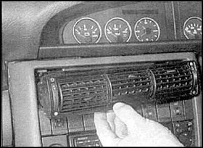
2. If necessary, remove the switch panel and then remove the switch.


3. If the wire is not long enough, remove the grille.
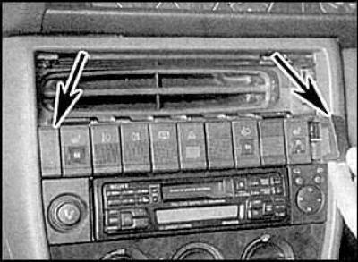


3. If the wire is not long enough, remove the grille.


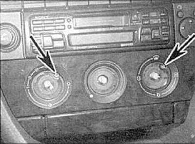
4. Remove the plugs (indicated by arrows).
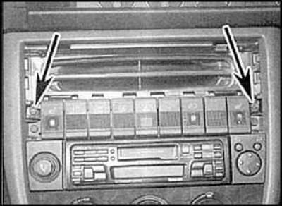
4. Remove the plugs (indicated by arrows).


5. Loosen the mounting screws (indicated by arrows).
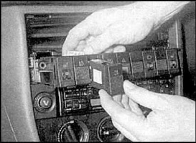
5. Loosen the mounting screws (indicated by arrows).


6. Disconnect the connection connector and remove the switch.

Installation


Installation is carried out in the reverse order of removal.

Rear view mirror regulator


Removal
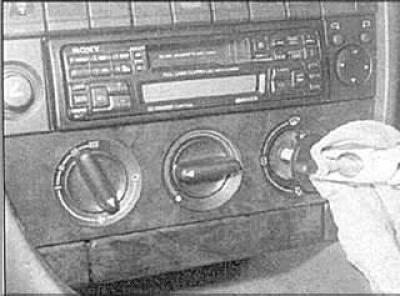


Removal


1. Remove the handles.


1. Remove the handles.


2. Loosen the mounting screws (indicated by arrows) and remove the panel.
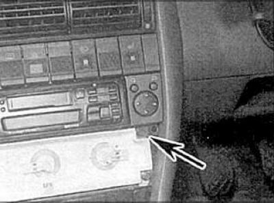
2. Loosen the mounting screws (indicated by arrows) and remove the panel.


3. Loosen the mounting screws.
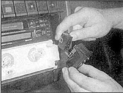
3. Loosen the mounting screws.


4. Remove the switch and disconnect the connection connector.

Installation


Installation is carried out in the reverse order of removal.

Driver's door window switches


Removal


Removal


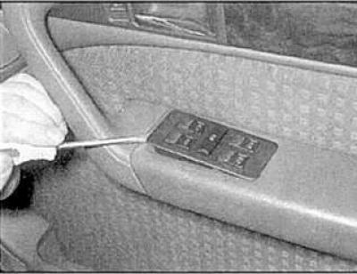
1. Remove the switch panel.


1. Remove the switch panel.


2. Disconnect the connection connectors.
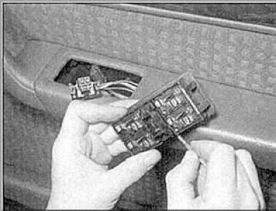
2. Disconnect the connection connectors.


3. Remove the switches.

Installation


Installation is carried out in the reverse order of removal.

Central lock switch on the driver's door


Removal
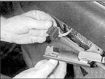


Removal


Remove the handle from the door. Remove the small trim panel, disconnect the connector and remove the switch.

Installation


Installation is carried out in the reverse order of removal.


Rear door window switch


Removal
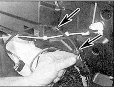


Removal


Remove the trim panel. Disconnect the connection connector, loosen the mounting clips and remove the switch.

Installation


Installation is carried out in the reverse order of removal.

Passenger door window switch


Removal
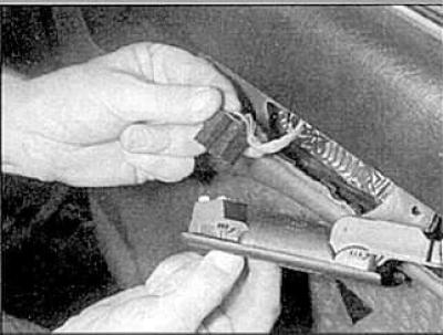


Removal


Remove the handle from the door. Remove the small trim panel, disconnect the connector and remove the switch.

Installation


Installation is carried out in the reverse order of removal.

Electric sunroof switch


Removal
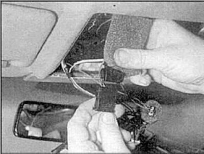


Removal


1. Remove the trim panel and disconnect the connection connectors.
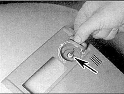


1. Remove the trim panel and disconnect the connection connectors.


2. Remove the handle and unscrew the mounting nut (indicated by the arrow).
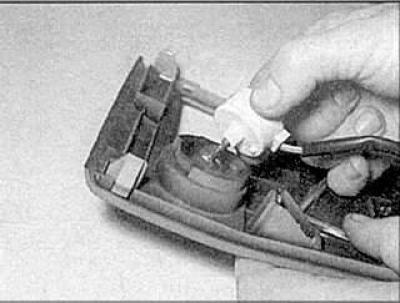
2. Remove the handle and unscrew the mounting nut (indicated by the arrow).


3. Remove the switch.

Installation


Installation is carried out in the reverse order of removal.

Interior light switch


Removal


Removal


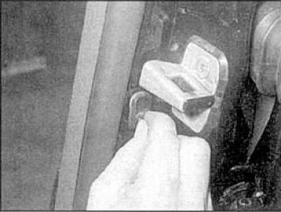
1. Remove the cover.

1. Remove the cover.


2. Loosen the mounting screw.
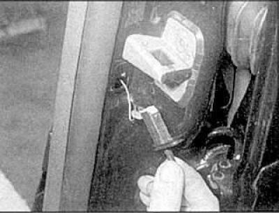
2. Loosen the mounting screw.


3. Remove the switch.

Installation


Installation is carried out in the reverse order of removal.

Brake light switch


Look subsection 10.21.

Switch on the handbrake lever


Removal


1. Remove the rear section of the center console.
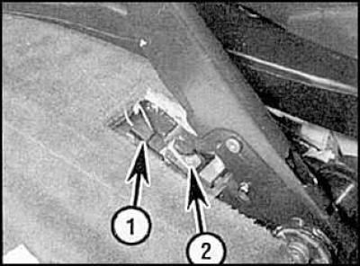
1. Remove the rear section of the center console.


2. Disconnect the connection connector (1), unscrew the fastening screw (2) and remove the switch.

Installation


Installation is carried out in the reverse order of removal.

Front seat power switch


Removal


Remove the trim panel. Unscrew the mounting screws and remove the switch.

Installation


Installation is carried out in the reverse order of removal.

Front Seat/Rear View Mirror Programmable Switches


Removal


Pry up the edge of the switch panel and remove the panel. Disconnect the connection connector.

Installation


Installation is carried out in the reverse order of removal.

Rear Seat Heater Switches


Removal


1. Remove the lighter and air duct.

2. Remove the switch.

Installation


Installation is carried out in the reverse order of removal.

Trunk light switch


Removal


Remove the trunk lock, release the retaining clip and remove the switch.

Installation


Installation is carried out in the reverse order of removal.
The article was checked by auto expert Georgy Rodionov
This article is available at russian, bulgarian, belarusian, ukrainian, serbian, croatian, romanian, polish, slovak, hungarian

Share information:
Previous articles
Audi A6 C4: Lighting and appliances
Next articles

Fuses and relays
Finding the source of a fault in an electrical system
Technical characteristics of electrical appliances
Replacing external lighting lamps
Replacing interior lighting bulbs
External lighting fixtures
Headlight adjustment


Similar articles on other Audi car models:
Switches on the control panel Audi 80 B3 (1986-1991, petrol)
Switches Audi 100 C3 (1982-1990, diesel)
Switches and switches Audi A3 Type 8L (1996-2003)
Lighting, light signaling and switches Audi A4 B5 (1994-2001, petrol)
Switches and switches Audi A8 D2 (1994-2002)
Lamps and switches in the instrument panel Audi Q5 Type 8R (2008-2017)
Removal and installation rear door window switches Audi A2 (1999-2005)
Link to this page in different formats


Visitor comments

No comments yet


How much will 11 + 21 =


A6(C5 AR, 1999-2005) 
  • General information
  • User manual
  • Maintenance
  • Troubleshooting
  • Power unit
  • V6 petrol engines
  • V8 petrol engines
  • Diesel engines
  • Cooling and heating system
  • Injection system (gasoline)
  • Fuel system (diesel)
  • Supply system
  • Exhaust system
  • Ignition system
  • Transmission
  • Clutch
  • Mechanical gearbox
  • Automatic gearbox
  • Chassis
  • Brake system
  • Car suspension
  • Steering
  • Body
  • Body elements
  • Doors, locks and windows
  • Electrical equipment
  • Equipment and devices
  • Power devices
  • Electrical circuits
  • Schemes (petrol engine 2.7 l)
  • Schemes (petrol engine 4.2 l)
  • Schemes (diesel engine 2.5 l)
 
A6(C5, 1997-2004) 
  • General information
  • User manual
  • Maintenance
  • Power unit
  • Engine repair
  • Cooling system
  • Fuel system
  • Engine management
  • Fuel system (diesel)
  • Exhaust system
  • Transmission
  • Clutch
  • Car gearbox
  • Chassis
  • Front suspension
  • Rear suspension
  • Steering
  • Wheels and tires
  • Brake system
  • Body
  • Exterior
  • Interior
  • Electrical equipment
  • Air conditioner
  • Equipment and devices
  • Electrical circuits
 
A6(C4, 1994-1997) 
  • General information
  • User manual
  • Maintenance (gasoline)
  • Maintenance (Diesel)
  • Gasoline engines
  • 4 cylinder engines
  • 5 cylinder engines
  • 6 cylinder engines
  • Diesel engines
  • 4 cylinder engines
  • 5 cylinder engines
  • Engine repair
  • Removal and reassembly
  • Cooling system
  • Single point injection system
  • Multipoint injection system
  • MPI/MPFI injection system
  • Fuel system (diesel)
  • Exhaust system
  • Ignition system
  • Transmission
  • Clutch
  • Manual transmission
  • Automatic transmission
  • Drive shafts
  • Chassis
  • Brake system
  • Front suspension
  • Rear suspension
  • Steering
  • Body
  • Exterior (external elements)
  • Interior (internal elements)
  • Electrical equipment
  • Power devices
  • Lighting and appliances
  • Electrical circuits
 
AudiManual.ru © 2017-2026 · Mobile version · Feedback · Sitemap: EN BG BY UA RS HR RO PL SK HU · Site search · News and articles
80 B2 · 80 B3 petrol · 80 B3 · 80 B4 · 100 C3 diesel · 100 C3 petrol · 100 C3 · 100 C4 petrol · 100 C4 · A3 Type 8L · A4 B5 petrol · A4 B5 · A4 B6 petrol · A4 B6 · A4 B7 · A4 B8 · A6 C4 · A6 C5 · A6 C5 Allroad · A8 D2 · Q5 Type 8R · Q7 Typ 4L · Audi A2 ·
This site uses cookies 🍪. Click the button to accept this fact.