
Caution! When opening the expansion tank, hot steam or hot coolant may come out, cover the cap with a rag and carefully open it. When the engine is warm, the cooling system is under pressure. If necessary, reduce the pressure before repair work. Use clamps of the appropriate series to secure all hose connections. The arrows on the ends of the pipes and hoses of the cooling system must be opposite each other.
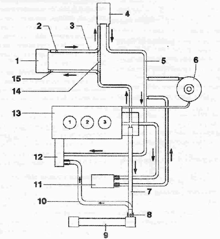
Coolant supply hose connection diagram:
1. EGR cooler or auxiliary heater. EGR cooler only for ATL engine, auxiliary heater depending on equipment
2. Air bleed screw plug
3. Coolant pipe
4. Heater heat exchanger. After replacement, drain the old coolant and fill it with new coolant
5. Coolant pipe
6. Coolant expansion tank with cap. Checking the pressure reducing valve in the expansion tank cap
7. Cooling system hose
8. Air bleed screw plug
9. Radiator. After replacement, fill with new coolant
10. Coolant supply hose
11. Oil radiator. After replacement, fill with new coolant
12. Cooling pump/thermostat
13. Cylinder head/cylinder block. After replacement, drain the old coolant and fill it with new coolant
14. Coolant pipe, for the heater heat exchanger of a vehicle without an EGR radiator or an independent heater
15. Coolant pipe, for EGR radiator or for independent heater
Text provided by the online resource AUDIMANUAL.RU