
Table of contents: CAN variants ↓ MMI variants ↓ Plug-in output connectors for… ↓ Plug-in output connectors for… ↓ Plug-in output connectors for… ↓ Multi-pin connector, 5-pin (T5g)… ↓ Removal the output for external… ↓ All ↓ Install ↓ Removal the output for external… ↓ Removal the connector for connecting… ↓
The "R199" external audio source output is available in several versions.
CAN variants
AMI Option (Audi Music interface) installed in the glove compartment.
The version with the Aux-In output is installed in the storage compartment of the central console. These outputs for external audio sources "R199" are connected directly to the radio "R". Either the AMI output or the Aux-In socket is installed.
MMI variants
AMI Option (Audi Music Interface) is a component of the used communication electronics 1 "J794". The interface is located in the glove compartment. The version with the Aux-In output is installed in the storage compartment of the center console. These outputs for external audio sources "R199" are connected directly to the used communication electronics 1 "J794". Either an AMI output or an Aux-In jack is installed. Various external audio sources can be connected to the connection of external audio sources "R199": iPod, MP3 "player, USB" drive. The appropriate adapters and cables are required. Troubleshooting is carried out in the "Guided Troubleshooting" mode.
Plug-in output connectors for external audio sources "R199" AMI (CAN)
Multi-pin connector, 12-pin (T12t)
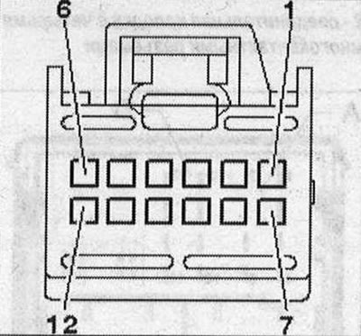 1. Terminal 31; 2. CAN-Infotainment Low; 3/5/6. not involved; 4. Low frequency output of the rights, to the radio "R"; 7. Terminal 30; 8. CAN-lnfotainment High; 9. Low frequency output left to radio "R"; 10. Low-frequency output (ground) to the radio "R".
Plug-in output connectors for external audio sources "R199" interface (MMI)
Multi-pin connector, 30-pin (T3d), black
All contacts are connected to used communications electronics 1 "J794".
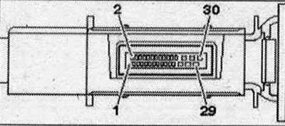 1. NF-ln on the left; 2. NF-ln on the right; 3. Mass NF; 4. NF-ln screen weight 13/14. iPod data; 16.iPod identification; 17. D(+); 18.D(-); 21. Detect; 22. Mass; 24. FBAS cable (-); 25. USB (mass); 27. FBAS cable (+); 28. USB (+5V)
Plug-in output connectors for external audio sources "R199" (Aux-lii)
Multi-pin connector, 4-pin (T4i) (CAN)
All contacts are connected to the radio "R".
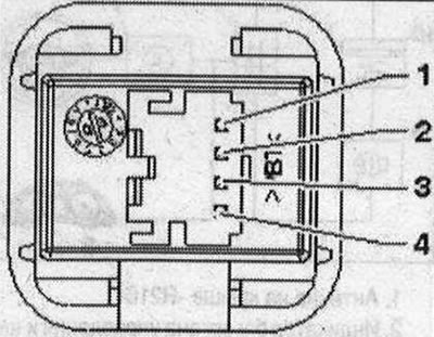 1. Mass NF; 2. NF on the left; 3. NF on the right; 4. Terminal 31
Multi-pin connector, 5-pin (T5g) (MM1)
All contacts are connected to used communications electronics 1 "J794".
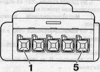 1. Mass NF; 2. NF on the left; 3. NF on the right; 4. Screen "mass"; 5. Detect.
Removal the output for external audio sources "R199" (AMI)
The output for external audio sources "R199" (AMI) is located in the glove compartment. Switch off all electrical consumers. Switch off the ignition. Open the glove compartment. Insert 2 brackets of the radio puller "T10057" into the slots to unlock the output for external audio sources "R199" until they click.
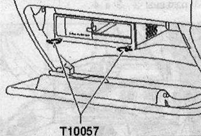
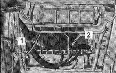
The ends of the tool loops are facing outward. Remove the output for external audio sources "R199" from the mounting frame. Disconnect the plug connectors of the output for external audio sources "R199".
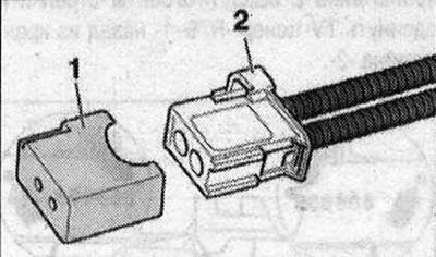
Option with MOST bus: Insert protective cap for cable plugs "VAS 6223/9-1" into the plug-in connector of the MOST bus "2".
All
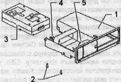
Take out the puller for the radio "T10057", to do this press the locking buttons on the output for external audio sources "R199". Remove the internal control unit. Unscrew the bolts "2" (2 N·m) on the back side. Press the stops "4" and "5" down and up and move the control unit down "3", removing it from the frame "1".
Install
Connect all plug connectors. Insert the output for external audio sources "R199" into the mounting frame until it locks.
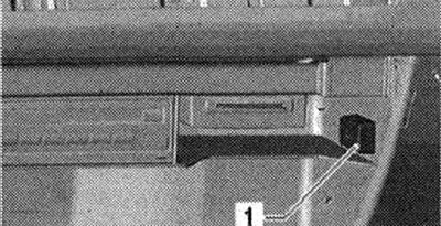
Removal the output for external audio sources "R199" (Aux-in)
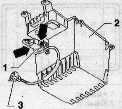
The output for external audio sources "R199" (Aux-in) is located in the storage compartment of the center console. Switch off all electrical consumers. Switch off the ignition. Remove the storage compartment of the center console. Disconnect the plug connector "3" of the output for external audio sources "R199" "1". Compress on output for external audio sources "R199" "1" "arrow" locks and free up the output for external audio sources "R199" "1" from storage compartment "2".
Installation in reverse order.
Removal the connector for connecting external audio devices "R199" (interface)
The output for external audio sources "R199" (interface) "1" is located in the glove compartment. Switch off all electrical consumers. Switch off the ignition. The interface wires are part of the wiring harness. They cannot be replaced separately. If damaged, install a set of cable adapters. Open the glove compartment. Unlock the shield "1" using the wedge "VAS 3409".
Interface (T30b) "1" is clipped into the back of the glove compartment.
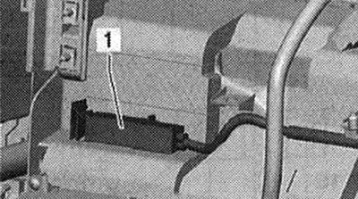
On the control unit of communications electronics 1 "J794" there are connectors to the interface T4ap "1" and T12u "2".
Installation in reverse order.
[The original article is available on the online resource AUDIMANUAL.ru]