



Table of contents: Chorus radio ↓ Concert tape recorder ↓ Symphony radio ↓ Electrical connectors "chorus" ↓ A - AM/FM1/FM2 antenna output ↓ B - connector block with four… ↓ A - multi-pin connector, 8-pin… ↓ B - multi-pin connector, 12-pin… ↓ C - multi-pin connector, 12… ↓ D - multi-pin connector, 8-pin… ↓ System connectors… ↓ 1 - AM/FM1/FM2 Antenna Output ↓ 2 - Multi-pin connector, 10-pin… ↓ 4 - connector block with four… ↓ A - Multi-pin connector, 8-pin… ↓ B- multi-pin connector, 12-pin… ↓ ↓ D - Multi-pin connector, 8-pin… ↓ Display connectors (CAN) ↓ Removal the radio "R" ↓ Install ↓ Removal the display ↓
Chorus radio
Radio with built-in CD player
Acoustic systems: basic/basic plus
Display Low
Mobile phone connection kit
Connecting external audio sources "R199"
Optional
Audio system: Standard
Preparing for installation of mobile phone.
Bluetooth hands-free device
Concert tape recorder
Radio with built-in CD player (mp3)
Acoustic systems: basic/basic plus/Standard
Display Mid
Mobile phone connection kit
SD memory card reader
Optional
Audio system: Bang & Olufsen
Preparation for installation of mobile phone
Bluetooth hands-free device
Digital radio "R147" integrated into concert
Connecting external audio "sources" R199-
Symphony radio
Radio with built-in
CD changer
Acoustic systems: basic/basic plus/Standard
Display Mid
Mobile phone connection kit
SD memory card reader
Optional
Audio system: Bang & Olufsen
Preparation for installation of mobile phone
Bluetooth hands-free device
Digital radio "R147" integrated into symphony
Connecting external audio "sources" R199-
Data transmission to other vehicle systems is carried out using the CAN bus
(Infotainment) and diagnostics of the data bus interface "J533". Troubleshooting is carried out in the "Guided Fault Finding" mode.
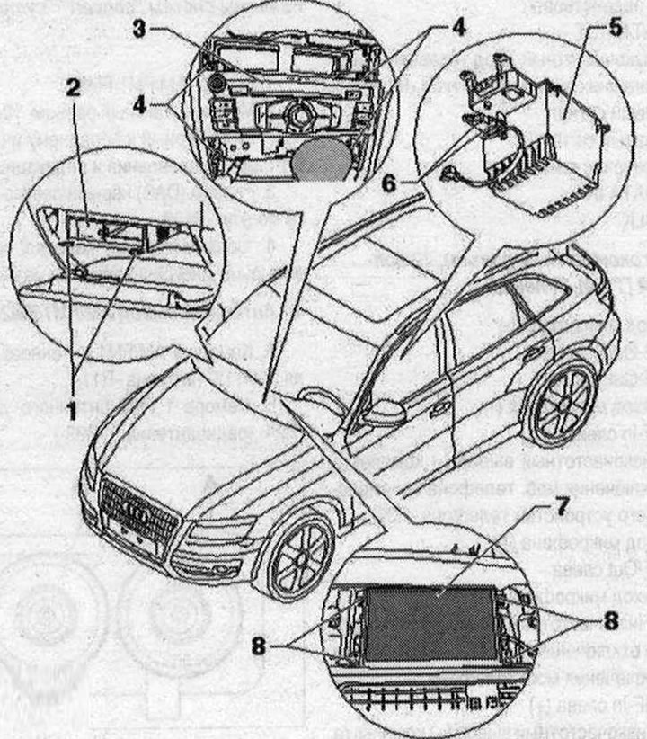
Installation diagram 1. Radio remover "T10057"; 2. Output for external audio sources "R199" (AMI); 3. Radio "R"; 4. Bolt 3 Nm; 5. Storage compartment; 6. Connecting external audio sources "R199" (Aux-In); 7. Used control and indication device indicator, front "J685" (Display); 8. Bolt. 2 Nm
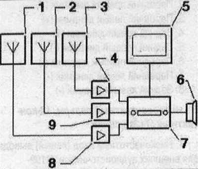
Radio installation device 1. Antenna of digital radio "R183" in the glass of the left side door; 2. Antenna "R11" in the spoiler; 3. Antenna 2 "R93" is installed in the rear window; 4. Antenna amplifier "R24" at the bottom of the trunk lid; 5. Used control and indication organ indicator, front "J685" in the front panel; 6. Acoustic systems; 7. Radio "R" in the dashboard; 8. Left antenna module "R108" on the D-pillar on the left; 9. Antenna amplifier 3 "R112" at the top of the trunk lid
Electrical connectors "chorus"
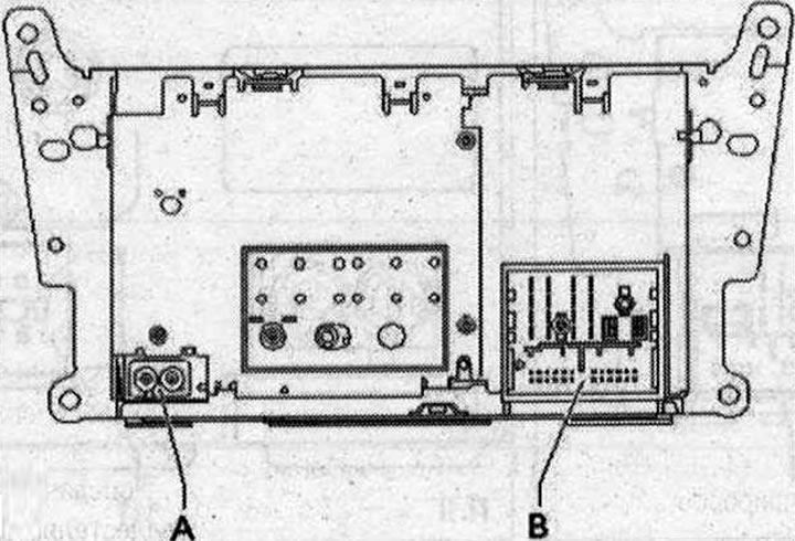
I A. Conclusion (AM/FM1/FM2); B. Connection block, black, with four multi-pin connectors.
Note: Plug contacts not specified are not used.
A - AM/FM1/FM2 antenna output
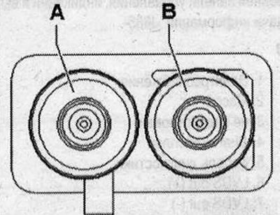
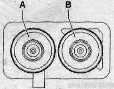
A. Chamber 2 AM/FM1 antenna amplifier 3 "R112" (antenna "R11"); B. Chamber 1 FM2 antenna amplifier "R24" (radio antenna 2 "R93")
B - connector block with four multi-pin connectors
A - multi-pin connector, 8-pin (T8k), brown
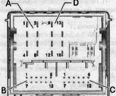
1. Rear right speaker (+); 2. Front right speaker (+); 3. Front left speaker (+); 4. Rear left speaker (+); 5. Rear right speaker (-); 6. Front right speaker (-); 7. Front left speaker (-); 8. Rear left speaker (-)
B - multi-pin connector, 12-pin (T12s)
- 1. Low frequency input (left) output for external audio sources "R199"
- 2. Low frequency input (left) output for external audio sources "R199"
- 3. Mass
- 4. Constant plus
- 5. not involved
- 6. DATA OUT
- 7. Low frequency input (right) output for external audio sources "R199"
- 8. Left signal
- 9. Right signal
- 10. included plus
- 11. DATA IN
- 12. CLK
C - multi-pin connector, 12 "contact" (T12a), green
- 1. Microphone input (-)
- 2. NF-Out on the right
- 3. NF-Out mass
- 4. Microphone output (-)
- 5. NF-ln left (-)
- 6. Low frequency terminal (-) of the mobile phone/telephone transceiver connection kit "R36"
- 7. Microphone input (+)
- 8. NF-Out on the left
- 9. Microphone output (+)
- 10. Low-frequency output for short-term microphone muting of the mobile phone connection kit
- 11. NF-ln left (+)
- 12. Low-frequency terminal (+) of the kit for connecting a mobile phone/telephone transceiver "R36"
D - multi-pin connector, 8-pin (T161) black
- 9. CAN-Infotainment High
- 10. CAN-Infotainment Low
- 11. Power supply to the front indicator unit with indicator and information "J685"
- 12. Terminal 31
- 13. CAN-Bus (display) to the front indicator of the used control and indication body "J685"
- 14. CAN-Bus (display) to the front indicator of the used control and indication body "J685"
- 15. Terminal 30
- 16. Constant plus (not used)
System connectors "concert"/"symphony"
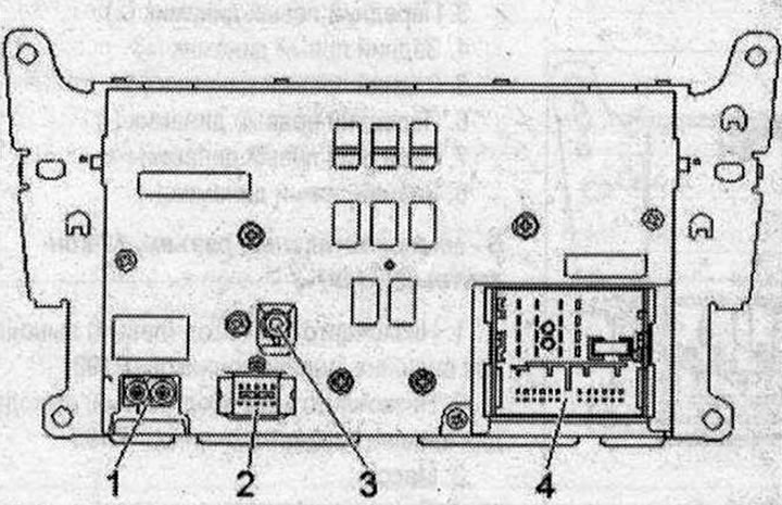
I 1. Conclusion (AM/FM1/FM2); 2. Multi-pin connector, 10 "pin" (T10v) black to the front indicator of the used control and indication panel "J685"; 3. Connector (DAB) black left antenna module "R108"; 4. Connector block, black, with four multi-pin connectors
1 - AM/FM1/FM2 Antenna Output
- A. Chamber 2 AM/FM1 antenna amplifier 3 "R112" (antenna "R11")
- B. Chamber 1 FM2 antenna amplifier "R24" (radio antenna 2 "R93")
2 - Multi-pin connector, 10-pin (T10v) black
- All contacts are connected to the display of the front control panel, indication and information output "J685".
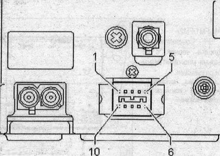
II 1. Power supply; 2. Mass; 3. not involved; 4. Diagnostic display; 5. Diagnostic cable; 6. LVDS out (+); 7. LVDSout (-); 8. LVDS out mass; 9. Diagn. T0; 10. Diagnostic T1 - connection block with four multi-contact connectors
4 - connector block with four multi-pin connectors
A - Multi-pin connector, 8-pin (T8k), brown
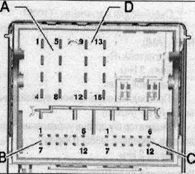
1. Rear right speaker (+); 2. Front right speaker (+); 3. Front left speaker (+); 4. Rear left speaker (+); 5. Rear right speaker (-); 6. Front right speaker (-); 7. Front left speaker (-); 8. Rear left speaker (-)
B- multi-pin connector, 12-pin (T12s), blue
- 1. Low frequency input (left). Output for external audio sources "R199"
- 2. Low frequency input (left) output for external audio sources "R199"
- 3. Mass
- 4. Constant plus
- 5. not involved
- 6. DATA OUT
- 7. Low frequency input (right) output for external audio sources "R199"
- 8. Left signal
- 9. Right signal
- 10. included plus
- 11. DATA IN
- 12. CLK
C - Multi-pin connector, 12-pin (T12a), green
- 1. Microphone input (-)
- 2. NF-Out on the right
- 3. NF-Out mass
- 4. Microphone output (-)
- 5. NF-ln left (-)
- 6. Low frequency terminal (-) of the mobile phone/telephone transceiver connection kit "R36"
- 7. Microphone input (+)
- 8. NF-Out on the left
- 9. Microphone output (+)
- 10. Low-frequency output for short-term microphone muting of the mobile phone connection kit
- 11. NF-ln left (+)
- 12. Low-frequency terminal (+) of the mobile phone/telephone transceiver connection kit "R36"
D - Multi-pin connector, 8-pin (T16I) black
- 9. CAN-Infotainment High
- 10. CAN-Infotainment Low
- 12. Terminal 31
- 15. Terminal 30
- 16. Constant plus (not used)
Display connectors (CAN)
Used control and indication organ indicator, front "J685"
"Chorus" (T10u), red
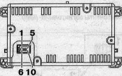
1. CAN-Bus (display) from the "R" radio; 2. CAN-Bus (display) from the "R" radio; 3. Radio power connector "R"; 4. Terminal 31
"Concert"/"symphony" (T10w), black
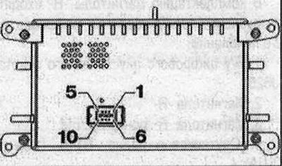
All contacts are connected to the radio "R". 1. Power supply; 2. Mass; 3. not involved; 4. Diagnostic display; 5. Diagnostic cable; 6. LVDSout (+); 7. LVDS out (-); 8. LVDS mass; 9. Diagn. T0; 10. Diagn. T1
Removal the radio "R"
When replacing a used one, select the "Replace" function of the corresponding used one in the "Guided Fault Finding" mode. Use a tester for this. Engage the parking brake. Switch off all electrical consumers. Move the gear selector/gearbox lever back as far as it will go. Switch off the ignition. Remove the air conditioning control unit. Remove the front panel deflector in the center. On the radio "R" "1" unscrew the bolts "arrows".
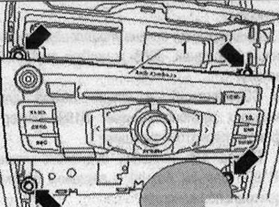
Remove the "R" "1" radio from the front panel. Unlock the connectors on the "R" radio and disconnect them.
Install
Installation in reverse order.
Removal the display
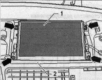
The used control and indicator, front "J685" (display) is located in the center of the dashboard. Switch off all electrical consumers. Switch off the ignition. Remove the MMI screen cover. On the front used control and indicator "J685" "1" unscrew the "arrow" bolts.
Remove the front indicator of the used control and indication body "J685" "1" from the front panel "2" and from the back side, disconnect the electrical connectors.
Installation in reverse order.
[The article was copied from the website AUDImanual]