



Table of contents: MMI minimum equipment ↓ MMI max compl. ↓ Used Electronic Communications… ↓ Notes on the MOST bus ↓ MMI connectors ↓ MMI max compl. ↓ Display connectors (MMI) ↓ All ↓ Removal the radio "R" MMI ↓ MMI Infotainment Center (USA) ↓ Notes on the MOST bus ↓
The MMI infotainment system is available in the following equipment versions:
MMI minimum equipment
Used infotainment electronics 1 "J794" in front panel includes CD player / SD card reader
The E380 multimedia system control in the lower part of the center console
Used control and indication organ indicator, front "J685" in the center of the front panel
CD changer "R41" / optional output for external audio sources "R199" (interface) in the glove compartment
Output for external audio sources "R199" (aux-In connector) in the storage compartment of the center console
Used digital audio package "J525" rear left in the trunk
Acoustic systems: basic/basic plus/Standard/Bang & Olufsen
Radio "R" in the trunk, rear left
Optional: mobile phone preparation
Bluetooth hands-free device (optional)
Optional multifunction steering wheel
MMI max compl.
Used communications electronics 1 "J794" in the front panel includes CD player / DVD player / Bluetooth / voice control / SD card reader
Internal hard disk drive (HDD) memory for storing navigation data and MP3 files
The E380 multimedia system control in the lower part of the center console
Used control and indication organ indicator, front "J685" in the center of the front panel
CD-changer "41" /optional output for external audio sources "R199" (interface) in the glove compartment
Output for external audio sources "R199" (aux-In connector) in the storage compartment of the center console
Used digital audio system "J525" rear left in the trunk
Acoustic systems: Standard/Bang & Olufsen
Radio "R" in the trunk, rear left
TV tuner "R78" in the trunk, rear left
Optional: mobile phone preparation
Bluetooth hands-free device (optional)
Optional multifunction steering wheel
Data exchange between MMI systems is carried out via the MOST bus. Connection to other bus systems is carried out via the diagnostic interface of the data bus "J533". Fault finding is carried out in the "Guided Fault Finding" mode.
Used Electronic Communications Design 1 "J794" (MMI)
I
Components of the radio "R" (MMI)
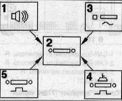
The "R" radio comes complete with the following control units, which are part of the 2nd generation: 1. Used digital acoustic package "J525"; 2. Radio "R"; 3. Radio "R" tuner AM/FM; 4. Satellite radio "R146" (only USA); 5. Digital radio "R147" (only Europe)
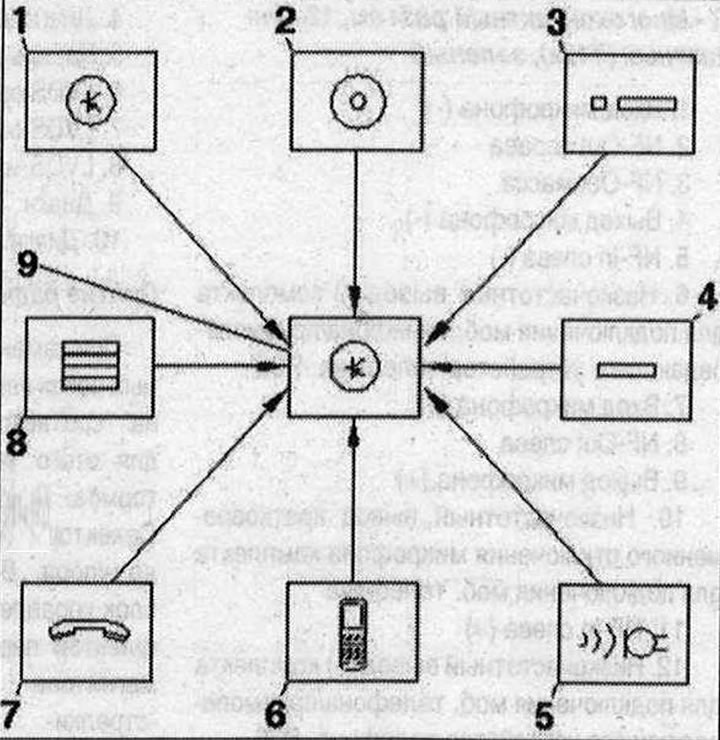
MOST bus components 1. Used control and indication device indicator, front "J685"; 2. Used electronic communications 1 "J794"; 3. MOST bus; 4. CD "changer-R41"; 5. TV tuner "R78"; 6. Radio "R"; 7. Used digital acoustic package "J525"; 8. Data bus diagnostic interface, "J533"; 9. Control unit of the multimedia system "E380"
Notes on the MOST bus
In addition to the CAN-BUS, the optical data bus "MOST-BUS" is used. A light guide is used as a "connecting cable". For protection, the light guides are laid in corrugated tubes. If possible, replace the optical cable completely. Make sure that the end surfaces of the plug connections are not contaminated. The plug connectors are disconnected: put on the protective cap for the cable plugs "VAS 6223/9".
When laying the light guides, observe the minimum bending radius of 25 mm. Do not squeeze or bend the light guides.
MMI 1. Radio remover "T10057"; 2. CD "changer-R41"; 3. Used electronic communications 1 "J794"; 4. Radio remover "T10057"; 5. Control unit of the multimeter system "E380"; 6. Wedge "3409"; 7. Nut. 3 Nm; 8. Radio "R"; 9. Bolt. 2Nm; 10. Used control and indication device indicator, front "J685" (Display)
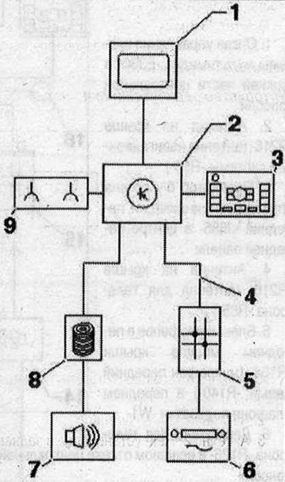
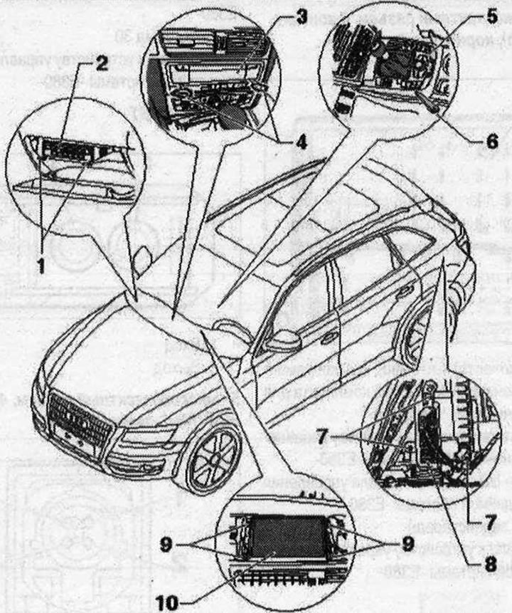
MMI components. Minimum configuration 1. Used control and indication organ indicator, front "J685" in the center of the front panel; 2. Used information electronics 1 "J794" on the front panel; 3. The control element of the multimedia system "E380" in the lower part of the central console; 4. MOST bus; 5. Data bus diagnostic interface "J533" behind the glove compartment on the left; 6. Radio "R" behind the left trunk trim; 7. Used digital audio system "J525" behind the left trunk trim; 8. CD changer "R41" in the glove compartment; 9. Output for external audio sources "R199" (aux-In connector) in the storage compartment of the center console
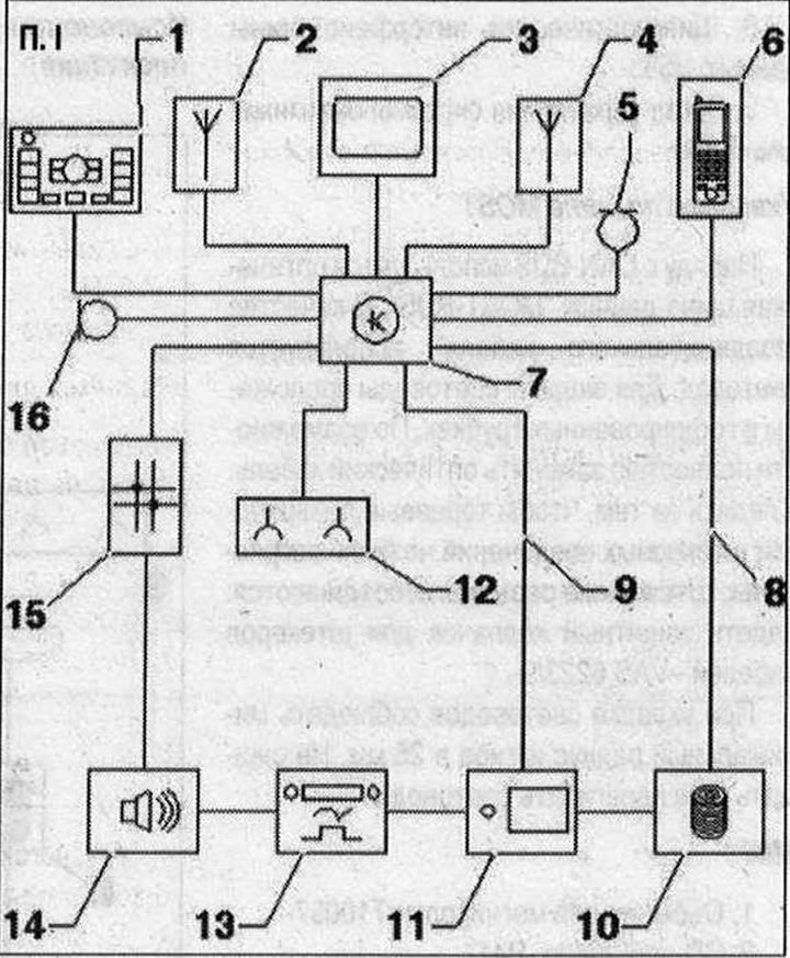
MMI Components. Maximum Equipment. I 1. The control element of the multimedia system "E380" in the lower part of the central console; 2. Roof antenna "R216" (navigation system antenna "R50"); 3. Used control and indication indicator, front "J685" in the center of the front panel; 4. Roof Antenna "R216" (Telephone Antenna "R65"); 5. Microphone unit in the front roof module "R164" (front left microphone "R140") in the front light "W1"; 6. Phone holder "R126" in the storage compartment of the central console; 7. Used information electronics 1 "J794" on the front panel; 8. MOST bus; 9. FBAS cable; 10. CD changer "R41" in the glove compartment; 11. TV tuner "R78" behind the left trunk trim; 12. Output for external audio sources "R199" (aUX-ln connector) in the storage compartment of the center console; 13. Radio "R" behind the left trunk trim; 14. Used digital audio system "J525" behind the left trunk trim; 15. Data bus diagnostic interface "J533" behind the glove compartment on the left; 16. Microphone unit in the front roof module "R164" (front right microphone "R141") in the front light "W1"
MMI connectors
MMI minimum equipment
Used Electronics Communications 1 "J794"
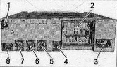
- 1/4/7/8 not used
- 2. Connector block with four multi-pin connectors
- 3. MOST bus
- 5. Multi-pin connector, 4-pin (T4al) to the front indicator of the used control and indicator panel "J685"
- 6. Multi-pin connector, 4-pin (T4ap) to the output for external audio sources "R199"
Note: Plug contacts not specified are not used.
2 - connection block with four multi-pin connectors
A - Multi-pin connector, 8-pin (T8ah), brown
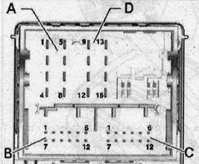
- 1. Low-frequency output for short-term microphone muting of the mobile phone connection kit
- 2. Power supply to the control unit of the multimedia system "E380"
- 3. Wake UP (start) to the control panel of the multimedia system "E380"
- 4/5. not involved
- 6. Res MU to the control unit of the multimedia system "E380"
- 7. Ring break diagnostic cable
B - multi-pin connector, 12-pin (T12x), blue
- 8. Microphone input (+) from the microphone unit in the front roof module "R164" (front left microphone "R140")
- 9. Microphone input (-) from the microphone unit in the front roof module "R164" (front left microphone "R140")
C - multi-pin connector, 12-pin (T12u), green
All contacts are connected to the output for external audio sources "R199".
- 1. NF-ln mass
- 2. NF-ln on the right
- 3. USB (+5V)
- 4. USB (mass)
- 5. not involved
- 6. Detect
- 7. NF-ln on the left
- 8. NF-ln screen mass
- 9. FBAS cable (+)
- 10. FBAS cable (-)
- 11. iPod data
- 12. iPod data
D - Multi-pin connector, 8-pin (T16q), black
- 10. Data from the control panel of the multimedia system "E380"
- 11. Data for the control panel of the multimedia system "E380"
- 12. Terminal 31
- 14. RES VT (stress test) from the control unit of the multimedia system "E380"
- 15. Terminal 30
- 16. Ground to the multimedia system control unit -E380
3 - MOST bus
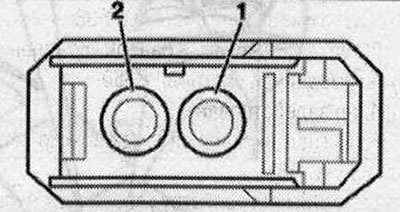
- 1. Login
- 2. Exit
5 - multi-pin connector, 4-pin (T4al), purple
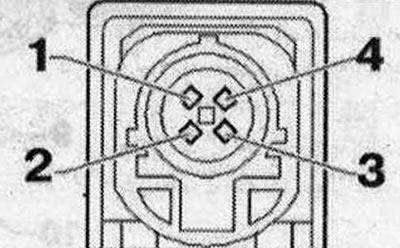
All contacts are connected to the display of the front control panel, indication and information output "J685".
- 1. Ivds (-)
- 2. UN
- 3. Ivds (+)
- 4. Mass
6 - multi-pin connector, 4-pin (T4ap)
All contacts are connected to the output for external audio sources "R199".
- 1. d(+)
- 2. iPod identification
- 3. D (-)
- 4. Mass
MMI max compl.
Used Electronics Communications 1 "J794"
- 1. GSM output from the roof antenna "R216"
- 2. Connector block with four multi-pin connectors
- 3. MOST bus
- 4. FBAS input (green) from TV tuner "R78"
- 5. Multi-pin connector, 4-pin (T4at) to the front indicator of the used control and indication panel "J685"
- 6. Multi-pin connector, 4-pin (T4ap) to the output for external audio sources "R199"
- 7. not involved
- 8. GPS output from the roof antenna "R216"
2 - connection block with four multi-pin connectors
A - Multi-pin connector, 8-pin (T8ah), brown
- 1. Low-frequency output for short-term microphone muting of the mobile phone connection kit
- 2. Power supply to the control unit of the multimedia system "E380"
- 3. Wake UP (start) to the control panel of the multimedia system "E380"
- 4. not involved
- 5. Signal to turn on the mobile phone amplifier "R86"
- 6. Res MU to the control unit of the multimedia system "E380"
- 7. Ring break diagnostic cable
B - multi-pin connector, 12-pin (T12x), blue
- 2. Microphone input (+) from the microphone unit in the front roof module "R164" (front right microphone "R141")
- 3. Microphone input (-) from the microphone unit in the front roof module "R164" (front right microphone "R141")
- 5. FBAS (-) cable from used rear view camera "J772"
- 8. Microphone input (+) from the microphone unit in the front roof module "R164" (front left microphone "R140")
- 9. Microphone input (-) from the microphone unit in the front roof module "R164" (front left microphone "R140")
- 11. FBAS (+) cable from used rear view camera "J772"
C - multi-pin connector, 12-pin (T12u), green
All contacts are connected to the output for external audio sources "R199".
- 1. NF-ln mass
- 2. NF-ln on the right
- 3. USB (+5V)
- 4. USB (mass)
- 5. not involved
- 6. Detect
- 7. NF-ln on the left
- 8. NF-ln screen mass
- 9. FBAS cable (+)
- 10. FBAS cable (-)
- 11. iPod data
- 12. iPod data
D - Multi-pin connector, 8-pin (T16q), black
- 9. Signal to turn on the phone holder "R126"
- 10. Data from the control panel of the multimedia system "E380"
- 11. Data for the control panel of the multimedia system "E380"
- 12. Terminal 31
- 13. DIAG signal from the phone holder "R126"
- 14. RES VT (stress test) from the control unit of the multimedia system "E380"
- 15. Terminal 30
- 16. Ground to the control unit of the multimedia system "E380"
3 - MOST bus
- 1. Login
- 2. Exit
5 - multi-pin connector, 4-pin (T4at) gray
All contacts are connected to the display of the front control panel, indication and information output "J685".
- 1. LVDS (-)
- 2. UN
- 3. LVDS (+)
- 4. Mass
6 - multi-pin connector, 4-pin (T4ap)
All contacts are connected to the output for external audio sources "R199".
- 1.D(+)
- 2. iPod identification
- 3. D(-)
- 4. Mass
Display connectors (MMI)
Used control and indication organ indicator, front "J685"
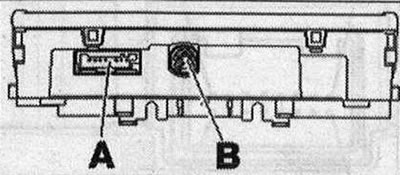
- A. Multi-pin plug connector, 8-pin (T8ai), black
- B. Multi-contact connector, 4-pin (T4ap/T4ao) used electronic communications 1 "J794"
A - Multi-pin connector, 8-pin (T8ai), black
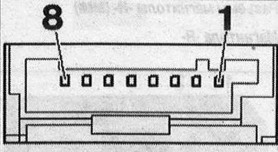
- 4. Terminal 30
- 5. Terminal 31
B - multi-pin connector, 4-pin (T4ap/T4ao), black/white
All contacts are connected to used communications electronics 1 "J794".
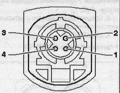
- 1. Ivds (-)
- 2. lin
- 3. Ivds (+)
- 4. Mass
Connectors of the control module of the multimedia system "E380"
Control unit of the multimedia system "E380"
Multi-pin plug connection, 16-pin
All contacts are connected to used communications electronics 1 "J794".
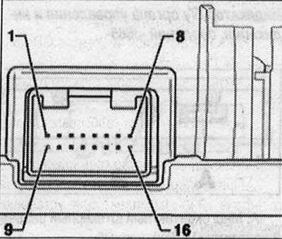
- 6. Wake UP signal
- 7. Power supply
- 8. Mass
- 13. Res HU
- 14. Res BT
- 15/16. Data
Radio connectors "R" (MMI)
Radio "R"
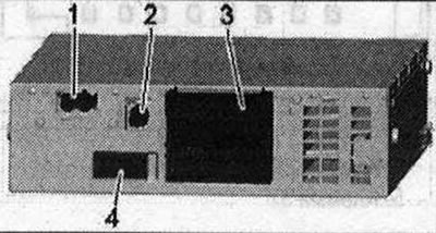
- 1. Conclusion (AM/FM1/FM2) from antenna amplifier "P24" / antenna amplifier 3 "P112"
- 2. Output (DAB) black from the left antenna module "P108" / antenna of the digital radio "P183"
- 3. Connector block with four multi-pin connectors
- 4. MOST bus
1 - AM/FM1/FM2 antenna output
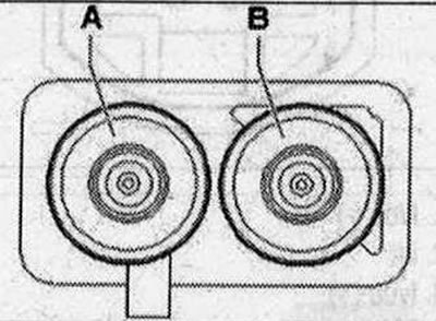
- A. Chamber 2 AM/FM1 antenna amplifier 3 "P112" (radio antenna 2 "P93")
- B. Chamber 1 FM2 antenna amplifier "P24" (antenna "P11")
3 - connection block with four multi-pin connectors
- A - multi-pin connector, 8-pin (T8ad), brown
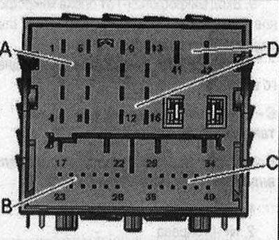
- 1. Rear right speaker (+)
- 2. Front right speaker (+)
- 3. Front left speaker (+)
- 4. Rear left speaker (+)
- 5. Rear right speaker (-)
- 6. Front right speaker (-)
- 7. Front left speaker (-)
- 8. Rear left speaker (-)
B - multi-pin connector, 12-pin (T12w), blue
- 17. NF-ln left
- 18. NF-ln mass
- 19. NF-ln diagnostics
- 21. NF Diagnostics
- 22. NF (-) mobile phone connection kit
- 23. NF-ln on the right
- 24. NF-ln screen mass
- 27. NF Screen mass
- 28. NF (+) mobile phone connection kit
C - multi-pin plug connection, 12-pin
- 29. Headphone output 1 diagnostics
- 31. Headphone output 1/2 diagnostics
- 34. Headphone output 2 diagnostics
- 35. Headphone output 1 left
- 36. Headphone output 1 mass
- 37. Headphone output 1 right
- 38. Headphone output 2 left
- 39. Headphone output 2 mass
- 40. Headphone output 1 right
D - multi-pin connector, 10-pin (T10ad), black
- 9. Subwoofer in the rear shelf "R157"
- 10. Central mid-range and high-frequency speaker "R1 SS"
- 11. Ring break diagnostic cable
- 13. Subwoofer in the rear shelf "R157"
- 14. Central mid-range and high-frequency speaker "R158"
- 41. Terminal 31
- 42. Terminal 30
4 - MOST bus
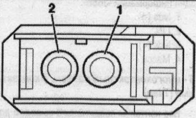
- 1. Login
- 2. Exit
Removal the control unit of the multimedia system "E380"
Apply the parking brake. Switch off all electrical consumers.
Cars with automatic transmission: Move the gear selector back as far as it will go.
All
Turn off the ignition. The used multimedia system "E380" is secured in the center console with springs "1" "arrows".
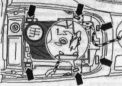
Remove the control panel "1" - climate, settings and unscrew the cover "2" of the gearbox lever upwards. Using the wedge "3409" unlock the springs of the "arrow" and remove the control unit of the multimedia system "E380" "3" from the central console upwards.
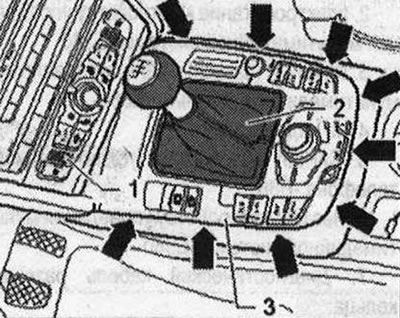
Take into account the length of the short wires going to the control panel of the multimedia system "E380", the electromechanical parking brake button "E538" and the access and engine start authorization button "E408". Disconnect all plug connectors from the back of the used multimedia system "E380". Remove the electromechanical parking brake button "E538" and the access and engine start authorization button "E408".
Installation in reverse order.
Removal the radio "R" MMI
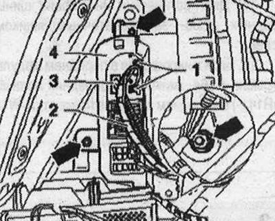
The "R" radio is located behind the left trim panel of the trunk. When replacing a used one, select the "Replace" function of the corresponding used one in the "Guided Fault Finding" mode. Use a tester for this. Switch off all electrical consumers. Switch off the ignition. Open the left compartment in the trunk. If available, first remove the lever for folding the towbar. On lever "1", unscrew the "arrow" bolts and tilt lever "1" away from the side wall "2" into the trunk compartment.

Disconnect connectors "2" and "3" from the radio "R" "4".
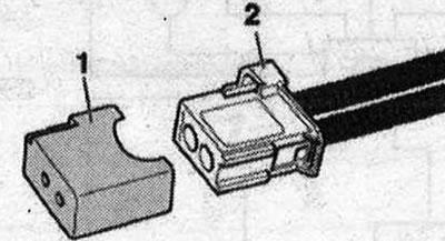
Insert the protective cap for the cable plugs "VAS 6223/9" 1- into the plug connector of the MOST bus "2".
Unscrew the nuts "arrows" on bracket "4". Turn the radio "R" with bracket "4" into the luggage compartment. Do not remove the used rear view camera "J772" attached to the bracket. The radio "R" is secured in the bracket with two clamps.
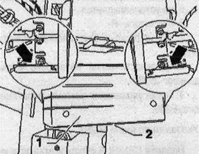
Press the "arrow" latches on the "R-2" radio and move the "R" "2" radio from the "1" bracket forward.
Installation in reverse order.
MMI Infotainment Center (USA)
The MMI infotainment centre is available in the following kit versions:
MMI maximum compl.
Used electronics communications 1 "J794" in the front panel includes CD "player / DVD" player / voice control / SD card reader
Internal hard disk drive (HDD) memory for storing navigation data and MP3 files
The E380 multimedia system control in the lower part of the center console
Used control and indication organ indicator, front "J685" in the center of the front panel
CD-changer "41" /optional output for external audio sources "R199" (interface) in the glove compartment
Output for external audio sources "R199" (aux-In connector) in the storage compartment of the center console
Used digital audio system "J525" rear left in the trunk
Acoustic systems: Standard/Bang&Olufsen
Radio "R" in the trunk, rear left, optional with satellite radio "R146"
Optional multifunction steering wheel
Bluetooth hands-free device (optional)
Data exchange between MMI systems is carried out via the MOST bus. Connection to other bus systems is carried out via the diagnostic interface of the data bus "J533". Fault finding is carried out in the "Guided Fault Finding" mode.
Used Electronic Communications Design 1 "J794" (MMI)
I
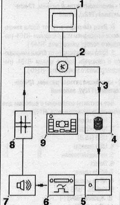
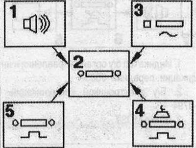
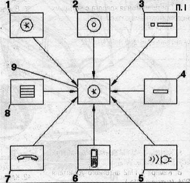
Used communications electronics 1 "J794" is a 3rd generation MMI. The used communications electronics 1 "J794" includes the following control units, which are part of the 2nd generation: 1. Used controls and indicators, front "J523"; 2. CD player "R89"; 3. Used navigation system with CD drive "J401"; 4. SD memory card reader; 5. Used voice command input systems "J507"; 6. Bluetooth hands-free device; 7. Transceiver for telephone "R36" (mobile phone installation kit); 8. Internal hard disk memory (HDD); 9. Used electronic communications 1 "J794"
Components of the radio "R" (MMI)
The "R" radio comes complete with the following control units, which are part of the 2nd generation: 1. Used digital acoustic package "J525"; 2. Radio "R"; 3. Radio "R" AM/FM tuner; 4. Satellite radio "R146"; 5. not installed
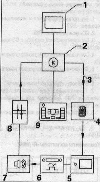
MOST bus components 1. Used control and indication device indicator, front "J685"; 2. Used electronic communications 1 "J794"; 3. MOST bus; 4. CD-changer "R41"; 5. not installed; 6. Radio "R"; 7. Used digital acoustic package "J525"; 8. Diagnostic interface of data bus "J533"; 9. Control unit of the multimedia system "E380"
Notes on the MOST bus
In addition to the CAN-BUS, the optical data bus "MOST-BUS" is used. A light guide is used as a "connecting cable". For protection, the light guides are laid in corrugated tubes. If possible, replace the optical cable completely. Make sure that the end surfaces of the plug connections are not contaminated. The plug connectors are disconnected: put on the protective cap for the cable plugs "VAS 6223/9".
When laying the light guides, observe the minimum bending radius of 25 mm. Do not squeeze or bend the light guides.
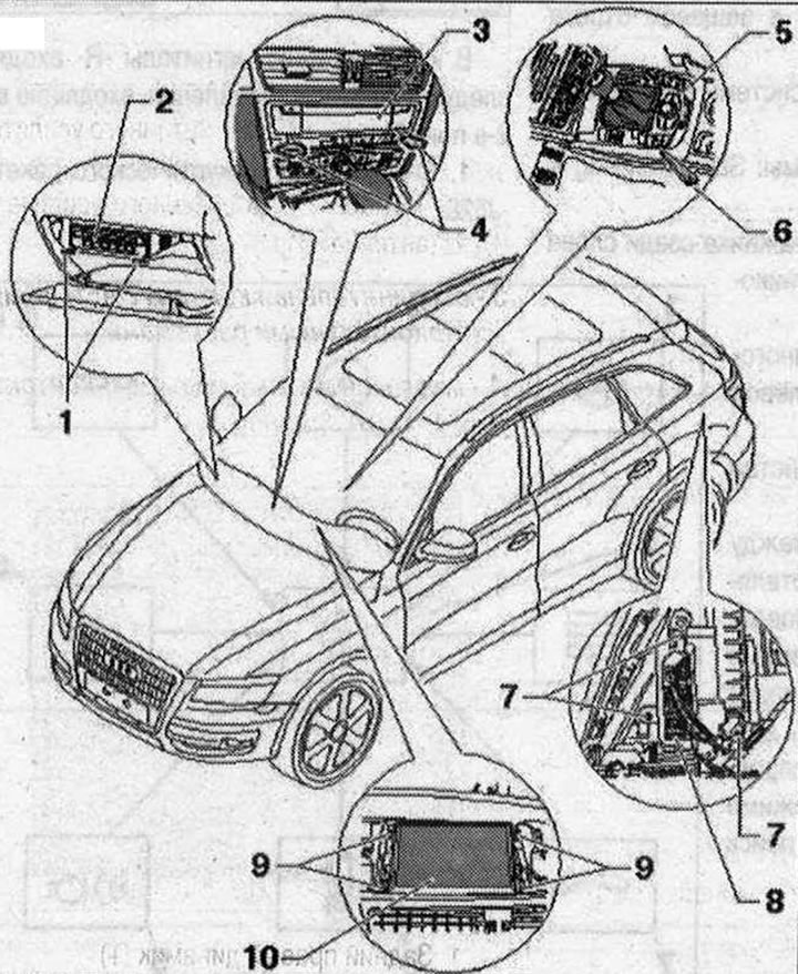
MMI 1. Radio remover "T10057"; 2. CD-changer "R41"; 3. Used electronic communications 1 "J794"; 4. Radio remover "T10057"; 5. Control unit of the multimedia system "E380"; 6. Wedge "3409"; 7. Nut. 3 Nm; 8. Radio "R"; 9. Bolt. 2 Nm; 10. Used control and indication device indicator, front "J685" (Display)
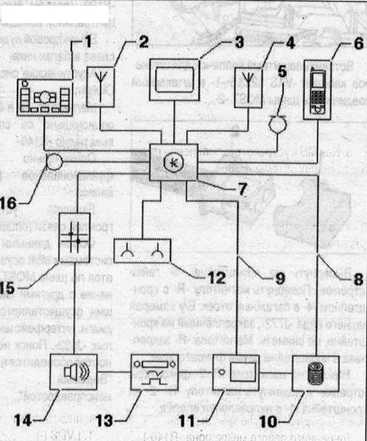
MMI Components 1. The control element of the multimedia system "E380" in the lower part of the central console; 2. Roof antenna "R216" (navigation system antenna "R50"); 3. Used control and indication indicator, front "J685" in the center of the front panel; 4. Roof Antenna "R216" (Telephone Antenna "R65"); 5. Microphone unit in the front roof module "R164" (front left microphone "R140") in the front light "W1"; 6/9/11. not installed; 7. Used information electronics 1 "J794" on the front panel; 8. MOST bus; 10. CD changer "R41" in the glove compartment; 12. Output for external audio sources "R199" (aUX-ln connector) in the storage compartment of the center console; 13. Radio "R" behind the left trunk trim; 14. Used digital audio system "J525" behind the left trunk trim; 15. Data bus diagnostic interface "J533" behind the glove compartment on the left; 16. Microphone unit in the front roof module "R164" (front right microphone "R141") in the front light "W1"
MMI connectors
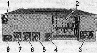
Used electronic communications 1 "J794" 1/4/7. not used. 2. Connection block with four multi-pin connectors; 3. MOST bus; 5. Multi-pin connector, 4-pin (T4at) to the front indicator of the used control and indication panel "J685"; 6. Multi-pin connector, 4-pin (T4ap) to the output for external audio sources "R199"; 8. GPS output from the roof antenna "R216"
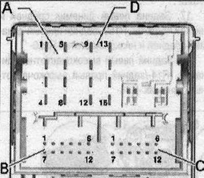
2 - connection block with four multi-pin connectors
A - Multi-pin connector, 8-pin (T8ah), brown
- 1/4/5. not involved
- 2. Power supply to the control unit of the multimedia system "E380"
- 3. Wake UP (start) to the control panel of the multimedia system "E380"
- 6. Res MU to the control unit of the multimedia system "E380"
- 7. Ring break diagnostic cable
B - multi-pin connector, 12-pin (T12x), blue
- Microphone input (+) from microphone unit in front roof module "R164" (front right microphone "R141")
- Microphone input (-) from microphone unit in front roof module "R164" (front right microphone "R141")
- FBAS (-) cable from used rear view camera "J772"
- Microphone input (+) from microphone unit in front roof module "R164" (front left microphone "R140")
- Microphone input (-) from microphone unit in front roof module "R164" (front left microphone "R140")
- FBAS (+) cable from used rear view camera "J772"
C - multi-pin connector, 12-pin (T12u), green
All contacts are connected to the output for external audio sources "R199".
- 1. NF-ln mass
- 2. NF-ln on the right
- 3. USB (+5V)
- 4. USB (mass)
- 5. not involved
- 6. Detect
- 7. NF-ln on the left
- 8. NF-ln screen mass
- 9. FBAS cable (+)
- 10. FBAS cable (-)
- 11/12. iPod data
D - Multi-pin connector, 8-pin (T16q), black
- 10. Data from the control panel of the multimedia system "E380"
- 11. Data for the control panel of the multimedia system "E380"
- 12. Terminal 31
- 14. RES VT (stress test) from the control unit of the multimedia system "E380"
- 15. Terminal 30
- 16. Ground to the control unit of the multimedia system "E380"
3 - MOST bus
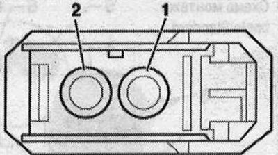
- 1. Login
- 2. Exit
5 - multi-pin connector, 4-pin (T4at) gray
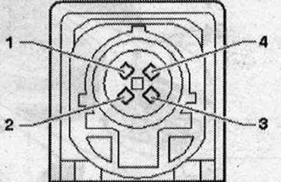
All contacts are connected to the display of the front control panel, indication and information output "J685".
- 1. LVDS (-)
- 2. UN
- 3. LVDS (+)
- 4. Mass
6 - multi-pin connector, 4-pin (T4ap)
All contacts are connected to the output for external audio sources "R199".
- 1. D(+)
- 2. iPod identification
- 3. D(-)
- 4. Mass
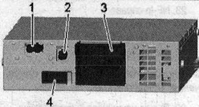
Radio connectors "R" (MMI) 1. Conclusion (AM/FM1/FM2); 2. Output (SAT) black from the roof antenna "R216" (satellite antenna "R170"); 3. Connector block with four multi-pin connectors; 4. MOST bus
1 - AM/FM1/FM2 antenna output
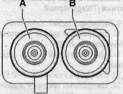
- A - Chamber 2 AM/FM1 antenna amplifier 3 "R112" (radio antenna 2 "R93")
- B - Chamber 1 FM2 antenna amplifier "R24" (antenna "R11")
3 - connection block with four multi-pin connectors
A - multi-pin connector, 8-pin (T8ad), brown

- 1. Rear right speaker (+)
- 2. Front right speaker (+)
- 3. Front left speaker (+)
- 4. Rear left speaker (+)
- 5. Rear right speaker (-)
- 6. Front right speaker (-)
- 7. Front left speaker (-)
- 8. Rear left speaker (-)
B - multi-pin connector, 12-pin (T12w), blue
- 17. NF-ln left
- 18. NF-ln mass
- 19. NF-ln diagnostics
- 21. NF Diagnostics
- 22. Low frequency output (-)
- 23. NF-ln on the right
- 24. NF-ln screen mass
- 27. NF Screen mass
- 28. Low frequency output (+)
C - multi-pin plug connection, 12-pin
- 29. Headphone output 1 diagnostics
- 31. Headphone output 1/2 diagnostics
- 34. Headphone output 2 diagnostics
- 35. Headphone output 1 left
- 36. Headphone output 1 mass
- 37. Headphone output 1 right
- 38. Headphone output 2 left
- 39. Headphone output 2 mass
- 40. Headphone output 1 right
D - multi-pin connector, 10-pin (T10ad), black
- 9. Subwoofer in the rear shelf "R157"
- 10. Central mid-range and high-frequency speaker "R1 Se"
- 11. Ring break diagnostic cable
- 13. Subwoofer in the rear shelf "R157"
- 14. Central mid-range and high-frequency speaker "R158"
- 41. Terminal 31
- 42. Terminal 30
4 - MOST bus
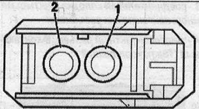
- 1. Login
- 2. Exit