
Diagram 4-22. Instrument cluster, diagnostic connector
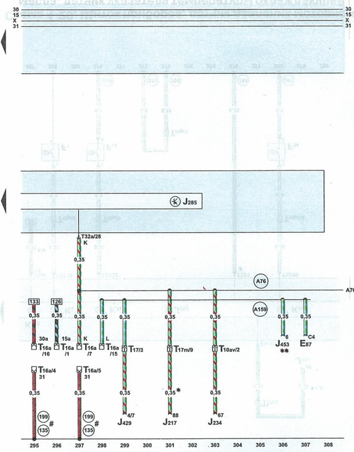
| E87 | heater/air conditioner switch block |
| J217 | automatic transmission control unit |
| J234 | airbag control unit |
| 3285 | combined processor on the instrument panel |
| J429 | central locking control unit |
| J453 | remote control processor. Cars with steering wheel with remote control buttons |
| T10av | 10-pin yellow plug on the front pillar on the right |
| T16a | 16-pin diagnostic connector plug |
| T17m | 17-pin blue plug on the front pillar on the right |
| T32a | 32-pin green plug on the instrument panel |
| 135 | ground (-) 2 in the instrument cluster wiring harness |
| 199 | ground (-) 3 in the instrument cluster wiring harness |
| A76 | wire K of the diagnostic connector in the instrument panel wiring harness |
| A159 | l wire in instrument cluster wiring harness |
| * | cars with automatic transmission 01V/01L |
| ** | cars with steering wheel with remote control buttons |
| # | both options are possible |