
Diagram 4-19. Instrument cluster, clock, brake pad wear indicator sensor, radio clock
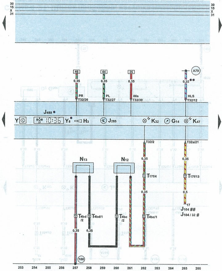
| G14 | voltmeter |
| NZ | buzzer/gong |
| J104 | ABS control unit with electronic differential lock (EDS) |
| J285 | microprocessor on the instrument panel |
| J489 | radio receiver with time of day indication |
| K32 | brake pad wear indicator light |
| K47 | ABS warning light |
| N12 | right brake pad wear sensor |
| N13 | left brake pad wear sensor |
| T4bc | 4-pin plug, black color ABS sensor left wheel |
| T4bd | 4-pin plug, black color, ABS sensor right wheel |
| T10ba | 10-pin blue plug on the left front pillar |
| T17f | 17-pin black plug on relay box under glove compartment on driver's side |
| T32 | 32-pin blue plug on the instrument panel |
| T32a | 32-pin green plug on the instrument panel |
| Y | pointer clock |
| Y8 | radio clock |
| 100 | wire 1 "ground" (-) in the ABS wiring harness |
| F79 | connection in the instrument panel wiring harness |
| * | cars with clock radios |
| ** | cars with parking heater |
| # | allroad cars with ABS 5.3 |
| ## | allroad cars with ABS 5.7 |
The article was copied from the website: audimanual