
Diagram 4-18. Instrument cluster, fuel gauge, coolant temperature gauge, tachometer, speedometer
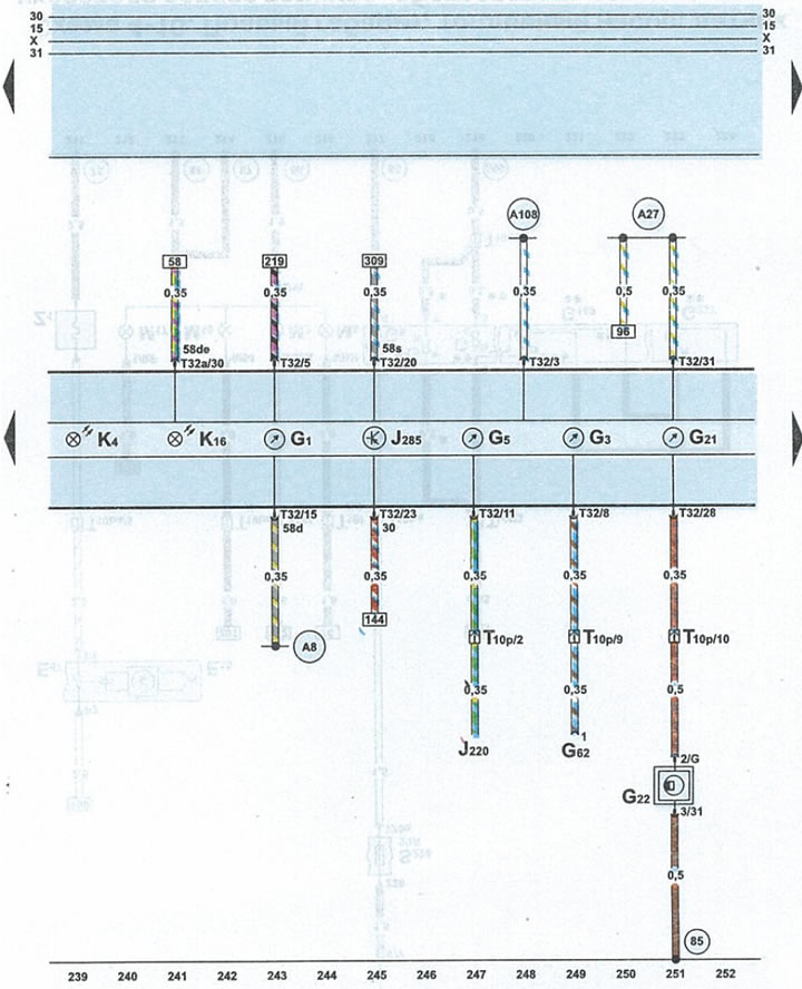
| G1 | fuel gauge |
| G3 | coolant temperature gauge |
| G5 | tachometer |
| G21 | speedometer |
| G22 | speedometer sensor (hall sensor on gearbox) |
| G62 | coolant temperature gauge sensor |
| J220 | engine control unit |
| J285 | instrument cluster microprocessor |
| K4 | parking light indicator |
| K16 | fuel reserve indicator light |
| T10p | 10-pin black plug for under cowl fuse/relay box |
| T32 | 32-pin blue plug on the instrument panel |
| T32a | 32-pin green plug on the instrument panel. |
| 85 | ground wire (-) 1 in engine compartment wiring harness |
| A8 | positive potential wire (terminal 58d) in the wiring harness on the instrument panel (display lighting) |
| A27 | wire from the speedometer sensor in the wiring harness on the instrument panel |
| A108 | wire from the speedometer sensor in the wiring harness on the instrument panel |