
Connection diagram of the components of the tempostat
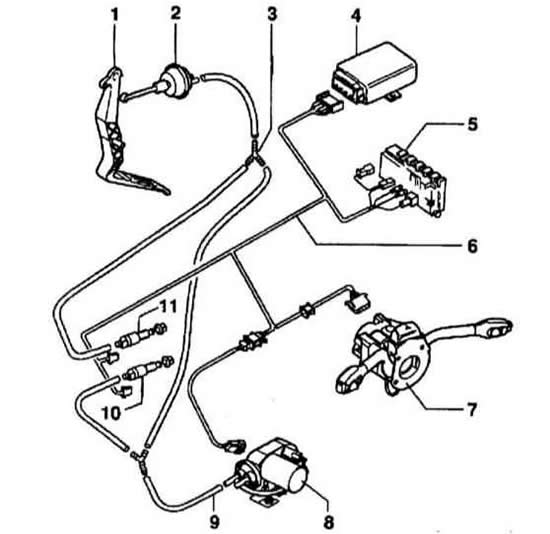
- 1 - Gas pedal
- 2 - Throttle control element
- 3 - T-shaped fitting
- 4 - Cruise control module (J213)
- 5 - Relay mounting block
- 6 - Wiring harness
- 7 - Cruise control switch (E45)
- 8 - Vacuum pump of the temperature controller (V18)
- 9 - Vacuum hose
- 10 - Clutch vacuum ventilation valve switch (F36)
- C - clutch pedal position sensor-switch
Only models with manual transmission
- 11 - Brake ventilation vacuum valve switch (F47)
Refer to the illustration and the schematic diagram of the electrical equipment of the tempostat.
The electrical connection diagrams below are based on the schematic principle, where the components of each circuit are connected to each other along the shortest path, without taking into account the shape of the wiring around the components and harnesses located along its path.
Audi A3 cars use a single-wire connection scheme for electrical equipment. Consumers are connected to the positive terminal of power sources by a wire, and to the negative terminal through the car body or to ground. This method reduces the number of wires and simplifies their installation. Connecting the negative terminal of power sources to ground reduces electrochemical corrosion of metal body parts. In some cases, direct connection of the electrical consumer to ground is not enough, and the consumer is connected to ground by an additional wire, usually brown.
Power supply to most consumers is supplied via the ignition switch. The power supply circuits of those electrical equipment units whose operation may be required under any circumstances are always connected to the battery, regardless of the position of the key in the ignition switch.
Electrical connectors with flat contacts are used to connect wires.
For normal power supply of consumers, the electric circuit must be closed, since otherwise there will be electric current in it, for example, if a positive voltage is supplied to the windshield wiper motor, it will not work until its electric circuit is connected to the ground. Switches, relays, fuses, measuring devices, electric motors and other consumers of electric power can be connected to the electric circuit. For the correct connection of consumers of electric power, the contacts of the electrical connectors have the appropriate markings. The connection to the ground of the car is carried out either directly through the body of the consumer of electric power or by an additional wire.
Contact 30
This contact always has positive battery voltage. The wires connected to this contact are red or red with a stripe.
Contact 31
The contact is connected to the vehicle ground with a brown wire.
Contact 15
This contact is supplied with positive voltage after the ignition is turned on. The wires connected to this contact are green or green with a stripe.
Contact X
The contact is supplied with voltage after the ignition is turned on, but when the starter is turned on, the voltage is disconnected. This makes it possible to turn off unnecessary consumers of electricity at this moment when starting the engine. The high beam headlights also receive power from this contact, so when the high beam is on and the ignition is turned off, an automatic switch to the parking lights occurs.
The colors of the wires are indicated by Latin letters.
If the wire color designation contains several letters separated by the / sign, then the left group of letters indicates the main color of the wire, and the right group indicates the color of the stripe.
bl | Blue
|
br | Brown
|
el | Cream
|
ge | Yellow
|
gn | Green
|
gr | Grey
|
hbl | Blue
|
hgn | Salad
|
li | Purple
|
nf | Transparent
|
og | Orange
|
rbr | Burgundy
|
ro, rt | Red
|
rs | Pink
|
sw | Black
|
vi | Violet
|
ws |
White |
In the diagram, all current consumers and switches are shown in the neutral position.
[A link to the original source is available on the website: Audimanual.ru]