



Table of contents: Remove the outer glass pressure plate ↓ Installation ↓
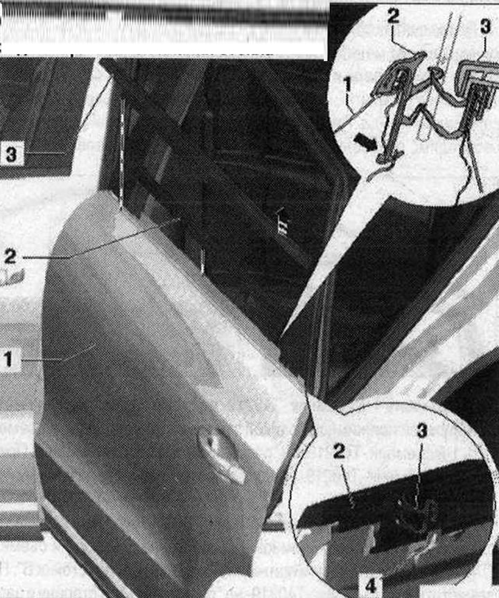
Installation diagram of the external and internal rear glass clamping strip 1. Door; 2. External glass clamping strip. Must be replaced after installation; 3. Inner pressure strip in the door cavity. Removal: door trim removed. Remove the pressure strip upwards; 4. Latch. 4x
Remove the outer glass pressure plate
After removal, the clamping strip must be replaced. The clamping strip 2 will gradually be completely unfastened and only then can it be removed upwards from the door flanging. Bring the door glass to the "open" position. The door trim has been removed. The C-pillar trim has been removed. Before removing the clamping strip "1", it must first be released from the door "arrow" latches.
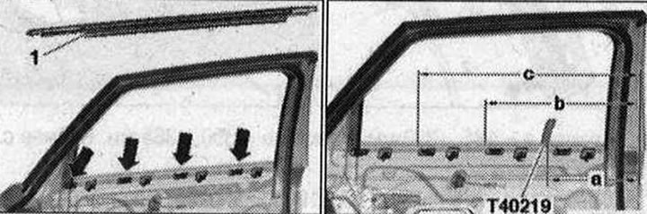
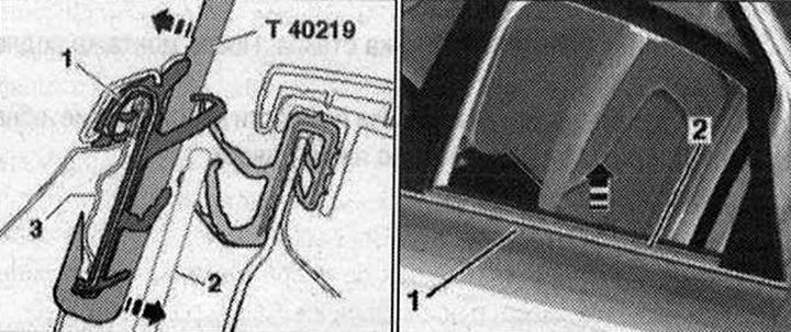
Insert the 1st puller "T40219" between the glass and the pressure bar on the C-pillar trim. Move the 1st puller "T40219" to the side and forward by "distance a". Pull the 1st puller "T40219" up and hook it onto the glass pressure bar.
The marking line on the puller "T40219" must be covered by the upper edge of the glass pressure bar. Insert the 2nd puller "T40219" between the glass and the pressure bar on the C-pillar trim. Move the 2nd puller "T40219" to the side by "distance b" and hook it from below. Insert the 3rd puller "T40219" on the C-pillar trim, move it to the side by "distance c" and hook it.
The starting point for measuring distances along the glass clamping bar is "pillar B"
Size a = 240...275 mm. Size b = 425...460 mm. Size c = 605...640 mm
Slightly press the "T40219" puller outward and unlock the glass pressure bar.
The pressure plate 2 is thereby gradually completely unfastened and only then can it be removed upwards from the door flange.
Installation
The latches on the outer door panel should not be bent and should not fit against the door glass, otherwise they will have to be bent back to their original position. Starting from the "B pillar", manually insert the outer pressure plate completely into the door latches.