



Table of contents: Active Brake Booster ↓ Used ABS with EDS/ASR/ESP J104 ↓ Brake Light Switch Relay J508 ↓ Steering Wheel Angle Sensor G85 ↓ Lateral acceleration sensor G200 ↓ Yaw rate sensor G202 ↓ ASR key E256 ↓ New Active ABS Sensor ↓ Operating principle of an active… ↓
Active Brake Booster
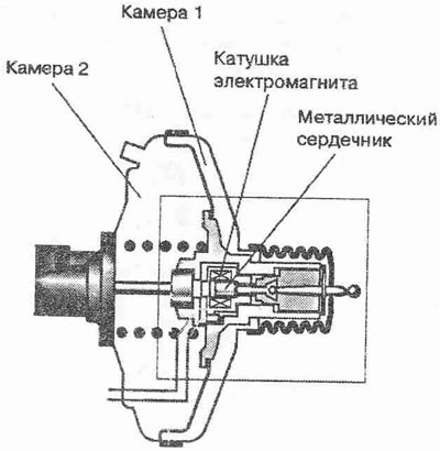
In addition to its usual task of increasing the force applied to the clutch pedal by means of the vacuum created by the intake manifold or vacuum pump, the brake booster also creates the pre-pressure required for the ESP to operate. The need for pre-pressure is caused by the fact that the return pump does not always have enough power to build up the required pressure due to the high viscosity of the brake fluid at low temperatures. When the ESP system needs to operate, the control unit signals the solenoid coil to move the metal core forward and open the valves inside the valve assembly. In this case, as when the brake pedal is pressed, the pressure in chamber 1 increases due to the resulting connection with the atmosphere (there is still a vacuum in chamber 2), at the same time, the amplifier creates pressure in the brake system, which is controlled by two sensors.
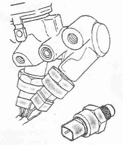
Sensor 1 (G201) and sensor 2 (G204) duplicate each other to ensure maximum reliability. These are capacitive sensors in the form of plate capacitors. When the moving plate is exposed to the pressure present in the brake system, the distance between the two plates decreases and the capacitor capacitance increases. The change in capacitance is directly proportional to the change in pressure and is used to calculate the braking forces and control the pumping.
Used ABS with EDS/ASR/ESP J104
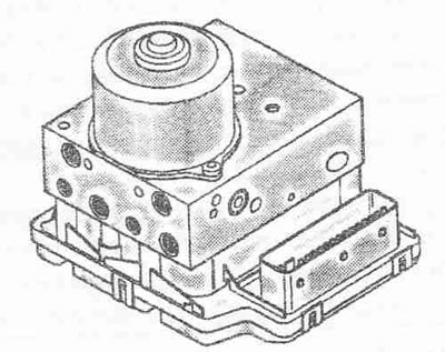
Used ABS/EDS 3104 is combined into one unit with a hydraulic block. Both blocks can be replaced separately without removing the entire unit.
Tasks: control of ESP, ABS, EDS, ASR, EBV and MSR functions; continuous monitoring of all electrical components; assistance in diagnostics during repair work.
Brake Light Switch Relay J508
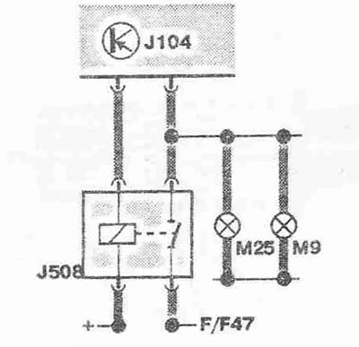
When the ESP system activates the solenoid coil, the brake pedal may move so far that it closes the brake light switch. In order not to mislead other road users, relay 3508 disconnects the connection to the lights while the solenoid coil is activated.
Steering Wheel Angle Sensor G85
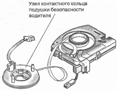
The spiral cable of the slip ring assembly connects the airbag control unit and the airbag module in the steering wheel. The G85 steering angle sensor is also installed in the housing of the slip ring assembly. It transmits the steering angle value to the 3104 control unit via the CAN bus. After replacing the spiral cable of the airbag/steering angle sensor, a basic setting must be performed. The G200 and G202 sensors are mounted on a common bracket, which is located near the center of gravity of the vehicle, on the tunnel between the center console and the bulkhead of the engine compartment.
Lateral acceleration sensor G200
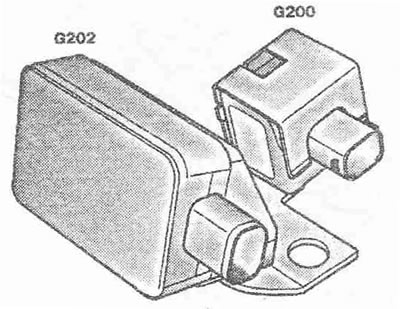
Measures lateral acceleration.
Yaw rate sensor G202
Measures the yaw angle of the vehicle (angle of rotation around the vertical axis). The signals from both sensors are needed by the J104 control unit to determine the actual state of the vehicle. They are used to calculate the control actions required to provide the vehicle with the required stability.
ASR key E256
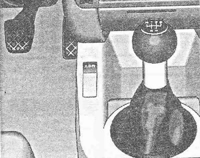
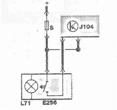
On the Audi A2 there is no option to turn off ESP. ASR can be turned off using the button (at a speed of 50 km/h).
New Active ABS Sensor
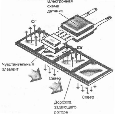
The sensor is called active when its operation requires external power supply. An active speed sensor has a magnetoresistive element whose resistance changes depending on the magnetic lines of force formed by the track of the sensor's driving rotor. The driving rotor of the sensor is mounted on the wheel hub and consists of a track with Sensitive sections magnetized in opposite directions. The ring rotates in front of the stationary sensitive element.
Operating principle of an active sensor
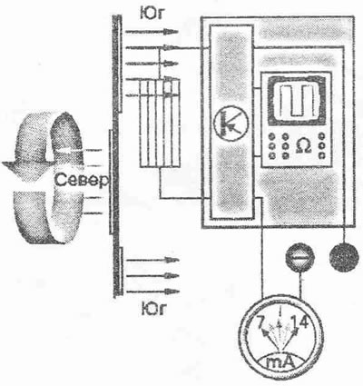
In the immediate vicinity of the magnetized section, the magnetic lines of force are perpendicular to the track. Depending on the pole facing the sensor, they are directed either towards or away from the sensor. Since the gap between the track and the sensor is very small, the lines of force pass through the sensing element and change its resistance. An electronic amplifier/trigger circuit built into the sensor converts the resistance changes into currents of two different levels. That is, when the resistance of the sensing element increases under the action of the magnetic lines of force passing through it, the current drops. When the direction of the lines of force changes to the opposite and the resistance decreases, the current increases. Since the north and south poles facing the sensor constantly alternate on the rotating track, a periodic rectangular signal is formed, the frequency of which is proportional to the rotational speed of the wheel.
Advantages: The wheel speed can be measured in any range from 0 km/h. The direction of wheel rotation is recognized. High corrosion resistance. Compactness.