
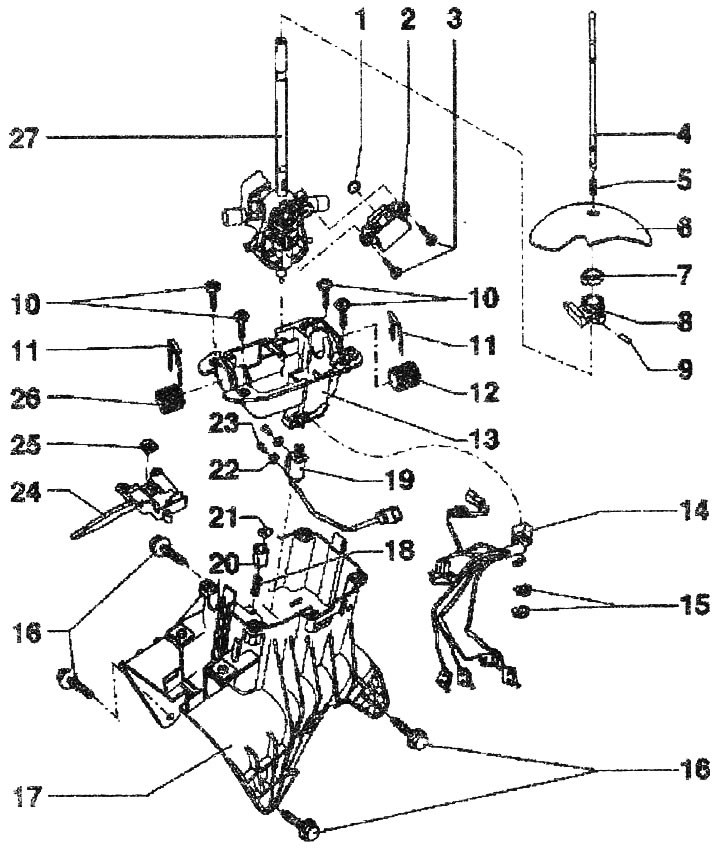
Gear shift mechanism drive:
1. O-ring. Replace
2. Selector potentiometer (forward/backward) "G272". Can be checked by measured values and during electrical testing
3. Bolt
4. Push rod
5. Pressure spring
6. Lid
7. Clamp
8. Retainer
9. Pin
10. Bolt, 5 Nm
11. Lock washer. Fixes the support sleeve "pos. 12" in the support plate "pos. 13". Mounting position: curved edge facing the selector
12. Support sleeve
13. Base plate
14. Cable harness with sensor for recognizing in which groove the selector lever of the automatic transmission is located "F257", sensor for recognizing the N position of the automatic transmission selector "F258", sensor for recognizing the "Stop" position of the automatic transmission selector "F259", sensor for recognizing the E position of the automatic transmission selector "F271". Can be checked by measured values and during electrical testing
15. Cable retainer
16. Bolt, 10 Nm
17. Shift mechanism housing
18. Pressure spring
19. Selector lock magnet AKIT "N110". Can be checked by measured values and during electrical testing
20. Bracket for fastening the roller "pos. 21". Mounting position: The roller fastening faces along the housing of the switching mechanism
21. Roller. Lubricate the sliding surfaces
22. Washer
23. Bolt
24. The stopper is inserted into the support plate and connected to the automatic transmission selector lock solenoid "N110"
25. Locking clamp
26. Support sleeve
27. Gear shift lever
The original material is located on the website AUDIMANUAL