
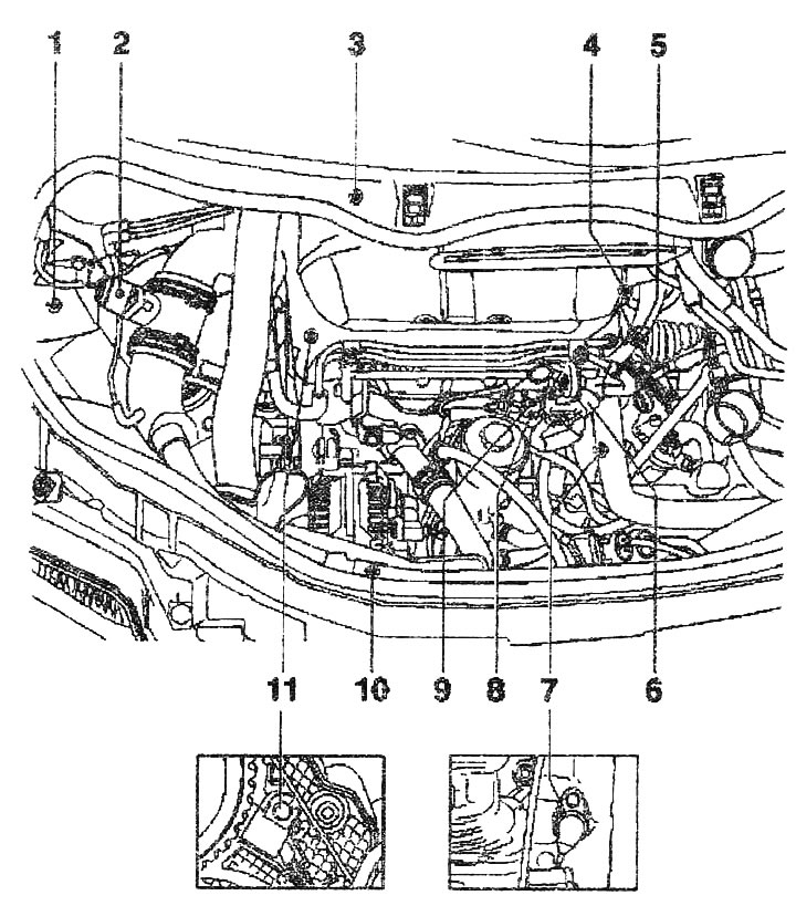
Installation locations of injection parts and units (bHC and ATL engines):
Nodes A through H are not shown in the drawing.
1. EGR valve "N18" and boost pressure limitation solenoid valve "N75"
2. Air flow meter "G70"
3. EGR valve with intake manifold flap
4. Coolant temperature sensor "G62"
5. Plug connector of the pump-injector module
6. Fuel temperature sensor "G81"
7. Engine speed sensor "G28"
8. Plug connector (gray) of engine speed sensor "G28"
9. Plug connector (black) of the Hall sensor "G40", for determining the position of the camshaft
10. Intake manifold pressure sensor "G71" with intake manifold temperature sensor "G72"
11. Hall sensor "G40" for determining the position of the camshaft
A. Brake pedal sensor "F47" in the footwell on the brake pedal
B. Brake light switch "F" in the footwell on the brake pedal
C. Accelerator pedal position sensor "G79" in the footwell on the accelerator pedal
D. Used direct injection diesel fuel systems "3248" with height sensor "F96"
E. Glow Plug Relay "352" (only VNS)
F. Used glow plugs "3179" (aTL only)
G. Power supply relay, cl. 30 "3317"
H. Used additional heater "3604" is installed in the additional electric heater (RTS)