
Functional diagram of the 1.4 l (55 kW) AUA engine
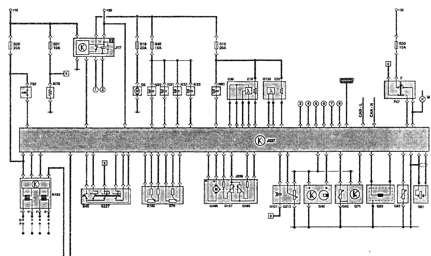
| E45 | Cruise control switch |
| E227 | Cruise control button |
| F | Brake light switch |
| F36 | Clutch pedal switch |
| F47 | Brake pedal switch |
| G6 | Fuel pump |
| G28 | Engine speed sensor |
| G39 | Lambda probe before the catalytic converter |
| G40 | Hall sensor |
| G42 | Intake Air Temperature Sensor |
| G61 | Knock Sensor 1 |
| G62 | Coolant temperature sensor |
| G71 | Intake Manifold Pressure Sensor |
| G79 | Accelerator Pedal Position Sensor |
| G130 | Lambda probe behind the catalyst |
| G185 | Accelerator Pedal Position Sensor 2 |
| G186 | Throttle actuator (electric accelerator drive) |
| G187 | Throttle Position Sensor 1 (electric accelerator drive) |
| G188 | Throttle Position Sensor 2 (electric accelerator drive) |
| G212 | EGR potentiometer |
| J17 | Fuel pump relay |
| J218 | Processor in the instrument cluster |
| J338 | Throttle body |
| J537 | 4LV injection system control unit |
| M9/10 | Left/Right Brake Light Bulb |
| N30...33 | Injectors for cylinders 1...4 |
| N79 | Heating resistor (crankcase ventilation systems) |
| N80 | Solenoid valve absorber |
| N121 | Modulated signal controlled EGR valve |
| N152 | Ignition coil |
| P | Spark plug wire tip |
| Q | Spark plugs |
| Z19 | Lambda probe heating element |
| Z29 | Lambda probe heating element 1, behind the catalytic converter |
Additional signals:
- (1) Impact signal, airbag control unit
- (2) Signal "Terminal 50", ignition switch
- (3) Generator, terminal DF
- (4) Speed signal (from the J218 processor)
- (5) Air conditioning compressor (increase in speed)
- (6) Fuel level in tank*
- (7) TD signal*
- (8) Air conditioning compressor
CAN bus H = CAN bus drive
CAN bus L = CAN bus drive
[x] Connection on the functional diagram
* not available with CAN-compatible J218 processor
The text is based on materials from the website: AUDIMANUAL.RU