



Instrument Cluster Control Unit, Radio Clock Receiver Module
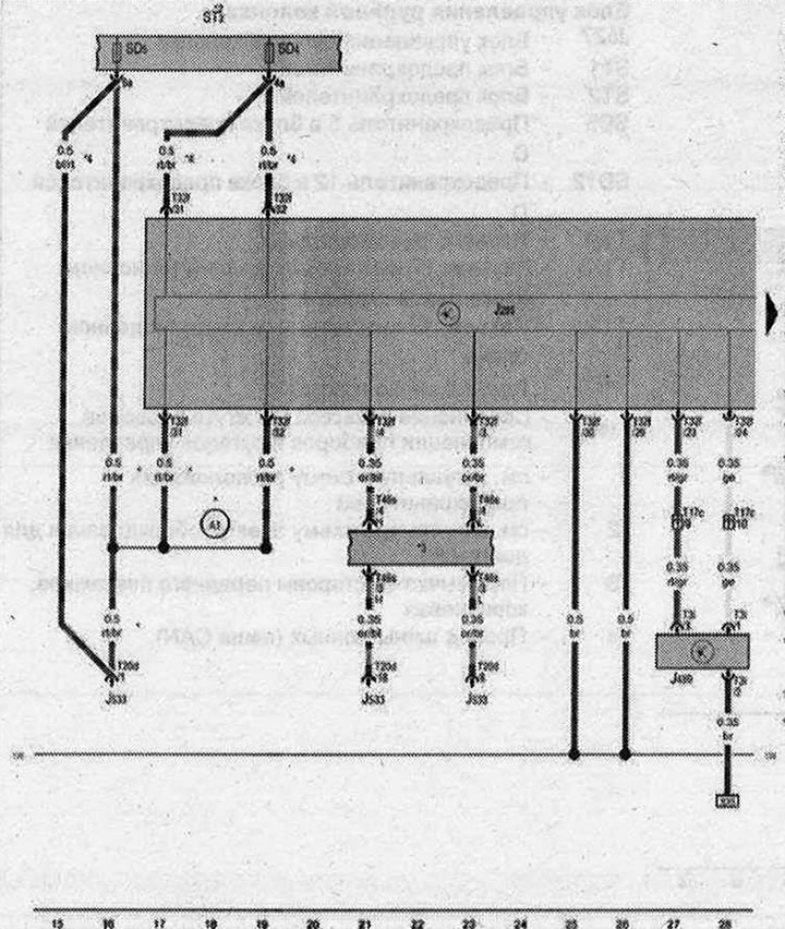
- J28S - Instrument cluster control unit
- J489 - Radio Clock Receiver Module
- JS33 - Data bus diagnostic interface
- ST2 - Fuse Box 2
- SD4 - Fuse 4 in fuse box D
- SD5 - Fuse 5 in fuse box D
- T3i - Connector, 3-pin
- T17c - Connector, 17-pin, in the junction box of the left A-pillar
- T20d - connector, 20-pin
- T32f - Connector, 32-pin
- T46s - Connector, 46-pin
- 135 - Ground connection 2 in instrument cluster and control wiring harness
- A1 - Positive connection (30A) in the instrument cluster and control wiring harness
- until April 2009
- 2 - see current fuse box diagram
- 3 - see the current electrical equipment diagram
- 4 - since May 2009
| ws | white | sw | black |
| ro | red | rt | red |
| br | brown | gn | green |
| bl | blue | gr | grey |
| li | purple | vi | purple |
| ge | yellow | or | orange |
| rs | pink |