
Table of contents: Removal ↓ Installation ↓
Removal
Using a screwdriver blade as a lever, remove the cap from the center of the wheel rim.
With the vehicle standing on its wheels, loosen the bolts securing the outer drive shaft joints to the front wheel hubs.
Raise the front of the car and secure it on stands. Remove the front wheels.
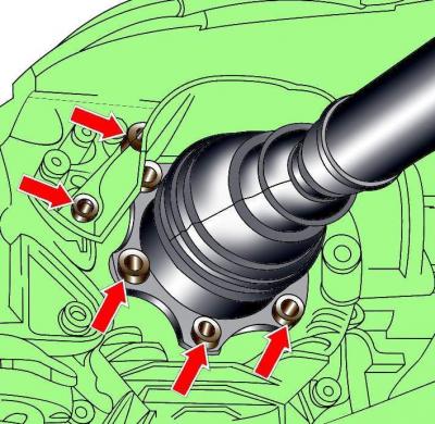
Fig. 10–2. Location of heat shield and drive shaft mounting bolts
Unscrew the mounting bolts and remove the heat shields of the right and left drive shafts (Fig. 10–2).
Remove the bolts and disconnect the inner drive shaft joints from the gearbox (see Fig. 10-2). Using soft wire, suspend the drive shafts from the body.
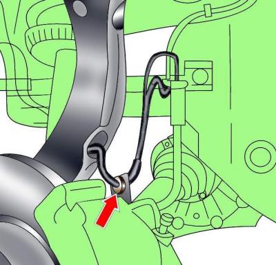
Fig. 10–3. ABS sensor wire mounting clamp location
Remove the ABS sensor wire from the front brake caliper clamp (Fig. 10-3).
Remove the ABS sensor from the steering knuckle.
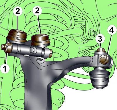
Fig. 10–4. Upper mount elements of the steering knuckle: 1 – nut and bolt for mounting the ball joints of the upper arms of the front suspension; 2 – ball joints of the upper arms of the front suspension; 3 – steering rod end mounting bolt; 4 – bolt with square head.
Unscrew the nut, remove the bolt securing the ball joints of the upper control arms of the front suspension to the steering knuckle (Fig. 10-4) and remove the ball joints from the steering knuckle. Do not widen the grooves in the steering knuckle when removing the upper control arms.
Do not loosen the tie rod end mounting bolt or the square head bolt, as this will affect the front wheel alignment.
Completely unscrew the bolt securing the drive shaft to the front wheel hub.
Tilt the top of the steering knuckle to the side, remove the drive shaft from the front wheel hub and remove the shaft from the vehicle.
Under no circumstances should the vehicle be lowered onto its wheels with one or two drive shafts removed, as this will damage the wheel hub bearings. If it is necessary to place the vehicle on its wheels and move it with the shafts removed, install its outer joint instead of the drive shaft and tighten the joint mounting bolt to 50 Nm.
Installation
Installation is carried out in the reverse order of removal, taking into account the following.
If the outer CV joint fails, it must be replaced. When installing it on the drive shaft, press the CV joint with a plastic hammer until it is secured with a retaining ring.
When installing, it is necessary to use new self-locking nuts and a bolt that secure the outer joint of the drive shaft to the hub, as well as new clamps and O-rings supplied with the repair kit.
Install the drive shaft into the front wheel hub and screw it to the gearbox drive flange, tightening the M8 bolts to 40 Nm and the M10 bolts to 70 Nm.
Install the upper wishbones until they stop against the steering knuckle and secure them with the bolt and nut, tightening to a torque of 40 N·m (see Fig. 10–4).
Install on steering knuckle ABS sensor.
Apply a thin layer of grease to the flange of the hub that centers the wheel disk. Install the wheel and secure it with bolts. Lower the car and tighten the wheel mounting bolts to the required torque.
Screw in and tighten the new bolts securing the outer joints of the drive shafts to the front wheel hubs to a torque of 190 N·m, and then tighten them an additional 180°. Tighten the bolts securing the drive shafts to the front wheel hubs only with the vehicle standing on its wheels.
(The original material is located on the website «Audimanual.ru»)