
Withdrawal
Remove the snap ring and end cap from the end of the CV joint.
Remove the inner CV joint from the drive shaft, for which screw the old bolt into the shaft, install the drive shaft cage on the tubular mandrel and, hitting the bolt with a plastic hammer, press the hinge housing onto the drive shaft, while holding the drive shaft at an angle of about 20°.
Remove the clamps securing the protective cover of the hinge and slide the cover onto the drive shaft.
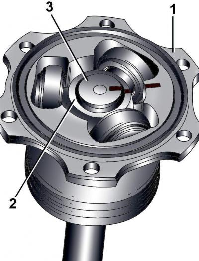
Pic. 10–8. Label that determines the relative position of the hinge body (1), clips (2) and drive shaft (3)
With a waterproof marker, mark the relative position of the hinge housing, cage and drive shaft (see fig. 10–8).
Remove the sealing ring from the end of the hinge housing.
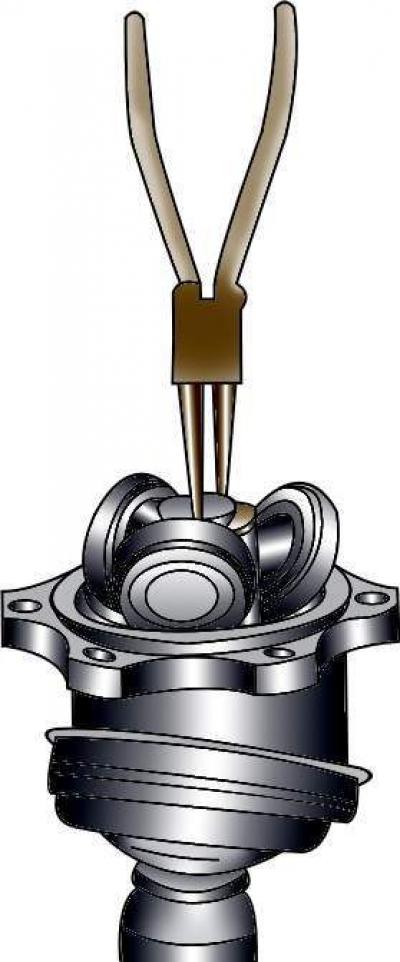
Pic. 10–9. Removing the retaining ring fastening the hinge holder to the drive shaft
Remove the retaining ring securing the joint holder to the drive shaft (pic. 10–9).
Using a puller, remove the pivot cage from the drive shaft.
Remove the pivot housing from the drive shaft.
Thoroughly clean the shaft and joint housing from grease.
Check the condition of the hinge cage, rollers and hinge housing.
Installation
Put on the drive shaft a small clamp for fastening the protective cover and a protective cover.
Install the hinge housing on the shaft.
Install the cage with rollers on the drive shaft and secure it with a retaining ring.
Apply 70 g of grease G 000 605 to the joint race on the side of the drive shaft and install the joint housing.
Apply 70 g of grease G 000 605 on the other side of the cage.
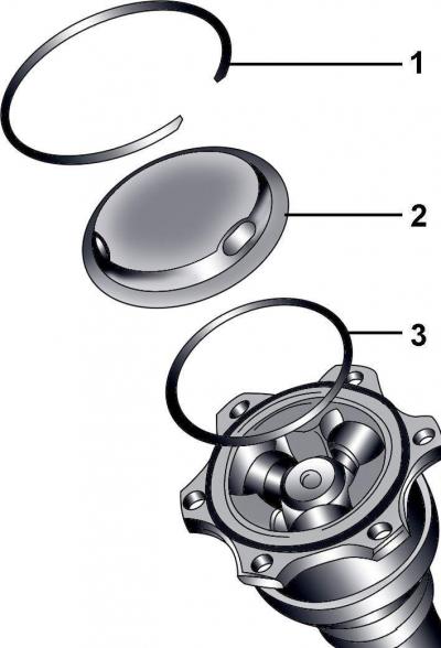
Pic. 10–10. Retaining ring location (1) lids (2) and sealing ring (3) at the end of the cage of the hinge of the drive shaft
Install the o-ring, cover and retaining ring on the end of the hinge housing (pic. 10–10).
Install the protective cover on the hinge and secure it with clamps, having previously lifted the inner edge of the cover with a screwdriver to equalize the air pressure under the cover.
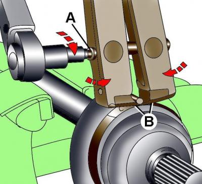
Pic. 10–7. The use of a special tool for fastening the clamp: A - a screw for tightening the jaws of the tool; B - installation of the jaws of the tool on the clamp
To fasten the clamps, use tool 1683 (see fig. 10–7). Install the jaws of the tool at the corners of the clamp clamp and in this position, compress the jaws with the screw, tightening it with a torque of 20 Nm.
Visitor comments