



Table of contents: Removal ↓ Installation ↓
Removal
On all-wheel drive vehicles, remove the rear section of the exhaust system.
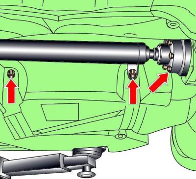
Fig. 15–38. Location of bolts for fastening the propeller shaft flange to the main rear gear and screws for fastening the heat shield
Loosen the screws and remove the central heat shield (see Fig. 15–38).
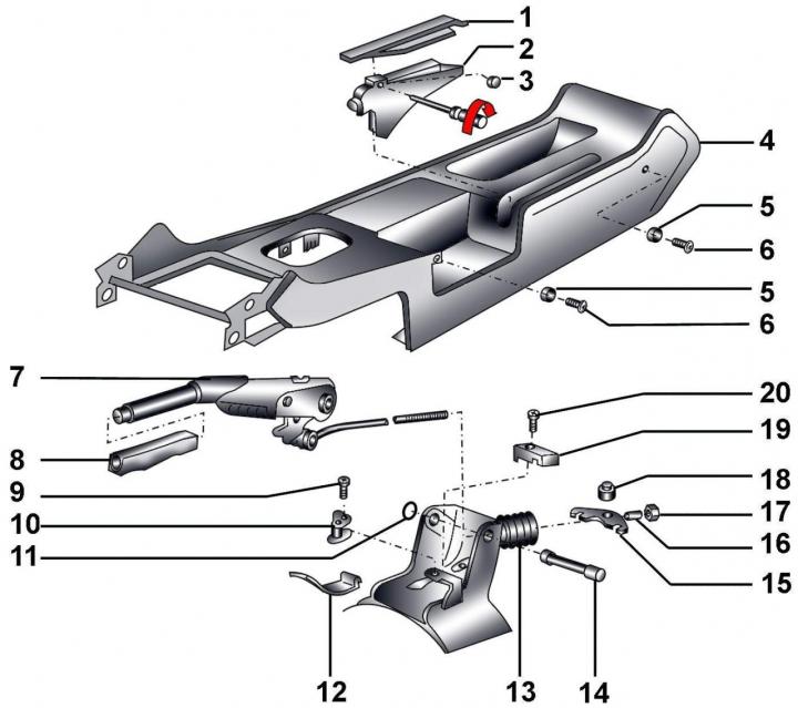
Fig. 15–33. Parking brake lever: 1 – decorative overlay; 2 – parking brake lever trim; 3 – lid; 4 – center console; 5 – washer; 6 – screw; 7 – parking brake lever; 8 – handle; 9 – self-tapping screw; 10 – Parking brake indicator lamp switch; 11 – retaining ring; 12 – spring; 13 – protective cover; 14 – hinge pin; 15 – compensator; 16 – bushing; 17 – adjusting nut; 18 – hinge pin; 19 – clamp; 20 – bolt, 5 Nm
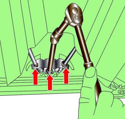
Fig. 15–34. Unscrewing the adjusting nut of the compensator mount and positioning the springs that secure the parking brake cable casings
Unscrew the adjusting nut securing the compensator to the parking brake lever rod (Fig. 15–34), remove the bushing and compensator.
Remove the protective cover from the parking brake lever rod.
Remove the center console.
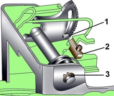
Fig. 15–35. Parking brake lever fastening elements: 1 – bolt; 2 – clamp; 3 – retaining ring
Unscrew bolt 1 and remove clamp 2 (Fig. 15–35).
Remove retaining ring 3 from the pivot pin and push out the pivot pin.
Move the parking brake lever slightly towards the rear and remove it.
Installation
Installation is carried out in the reverse order of removal, taking into account the following.
Before installing the lever, apply G 000 150 grease to all moving joints.
Install the retaining ring and check the tightness of the pivot pin.
Install the protective cover.
Check that the system is installed freely, without tension, with sufficient clearance from the body elements.
Adjust parking brake.