Repair Chevrolet Repair Toyota Repair Honda Repair AvtoVAZ Repair Mercedes-Benz Repair BMW Repair Opel
Home  |  Contacts  |  Sitemap  |    
English Русский
Български
Беларускі
Український
Српски
Hrvatski
Română
Polski
Slovenský
Magyar
AudiManual.ru


  • AUDI 80
  • AUDI 100
  • AUDI A3
  • AUDI A4
  • AUDI A6
  • AUDI A8
  • AUDI Q
  • OTHER
  • ARTICLES
C5 Allroad (1999-2005) C5 (1997-2004) C4 (1994-1997)

Wiring diagram of the instrument cluster display, combined display processor, control indicators, brake pad control indicators (Audi A6 C5)

  • Home
  • Audi A6
  • C5 (1997-2004)
  • Electrical equipment
  • Electrical circuits
  • Wiring diagram of the instrument cluster display, combined display processor, control indicators, brake pad control indicators
            0
Scheme 11. Display of the instrument cluster, combined display processor, control indicators, brake lining control indicators for vehicles with ASK, ALG, AGA and ALF engines

Scheme 11. Display of the instrument cluster, combined display processor, control indicators, brake…
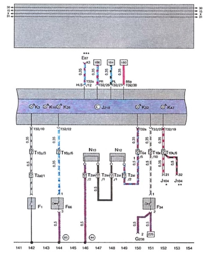
  • E 87 - air conditioner control unit and indicator panel
  • F1 - oil pressure switch
  • F 34 - brake fluid level safety contact
  • F 66 - Coolant temperature sensor switch
  • G 238 - Air quality sensor
  • J 104 - ABS control unit with EDS (Electronic differential lock system)
  • J 218 - Display Combination Processor
  • K 3 - oil pressure control indicator
  • K 16 - fuel level control indicator
  • K 28 - Coolant temperature control indicator / low coolant level sensor
  • K 32 - brake pad wear indicator
  • K 47 - ABS control indicator
  • N 12 - brake control relay (brake failure control element), on the right
  • N 13 - brake control relay (brake failure control element), left
  • T 2 ai - plug connection, 2-pin, black, oil sensors
  • T 2 ak - plug connection, 2-pin, red, on the front wall, left
  • T 2 al - plug connection, 2-pin, red, on the front wall, on the right
  • T 6 e - plug connection, 6-pin, grey, connecting clamp, A-post right
  • T 10 e - plug connection, 10-pin, color purple, connecting clamp, post A left
  • T 10 k - plug connection, 10-pin, orange, connecting clamp, post A left
  • T 10 p - plug connection, 10-pin, black, connecting clamp for water tank E-Box
  • T 32 - plug connection, 32-pin, blue, on the instrument cluster
  • T 32 a - plug connection, 32-pin, green color, on the instrument cluster
  • 44 - ground point, pillar A, bottom left
  • 85 - connection to the body ("ground") "1", in the wiring harness, engine compartment

* - cars with ABS


** - cars with ABS and ESP (exchange rate stabilization system)
*** - cars with air conditioning

[The original article is located on the online resource audimanual.ru]
The article was checked by auto expert Alexey Ivanov
This article is available at russian, bulgarian, belarusian, ukrainian, serbian, croatian, romanian, polish, slovak, hungarian

Share information:
Previous articles
Audi A6 C5: Electrical circuits
Next articles

Wiring diagram of the instrument cluster display, combined…
Electrical diagram of the instrument cluster display, control…
Electrical diagram of the fuel level control sensor, fuel pump,…
Electrical diagram of the Motronic control unit, air mass meter,…
Wiring diagram for instrument cluster display, display…
Wiring diagram of ignition switch and compensation relay for…
Wiring diagram for light switch, gear shift on steering column…
Electrical diagram of the light switch regulator and instrument…


Similar articles on other Audi car models:
Electrical Wiring Diagram for Knock Control System Audi 80 B3 (1986-1991, petrol)
Upper indicators in the instrument cluster Audi 100 C4 (1990-1994, petrol)
Instrument cluster unit, combi-processor in instrument cluster… Audi A3 Type 8L (1996-2003)
Central display of the instrument cluster, driver information… Audi A4 B7 (2004-2008)
Air Conditioning Control Audi A8 D2 (1994-2002)
Instrument cluster control unit, diagnostic connector, low brake… Audi Q7 Typ 4L (2005-2015, diesel)
Multi-pin connectors in the instrument cluster control unit Audi A2 (1999-2005)
Link to this page in different formats


Visitor comments

No comments yet


How much will 26 + 13 =


A6(C5 AR, 1999-2005) 
  • General information
  • User manual
  • Maintenance
  • Troubleshooting
  • Power unit
  • V6 petrol engines
  • V8 petrol engines
  • Diesel engines
  • Cooling and heating system
  • Injection system (gasoline)
  • Fuel system (diesel)
  • Supply system
  • Exhaust system
  • Ignition system
  • Transmission
  • Clutch
  • Mechanical gearbox
  • Automatic gearbox
  • Chassis
  • Brake system
  • Car suspension
  • Steering
  • Body
  • Body elements
  • Doors, locks and windows
  • Electrical equipment
  • Equipment and devices
  • Power devices
  • Electrical circuits
  • Schemes (petrol engine 2.7 l)
  • Schemes (petrol engine 4.2 l)
  • Schemes (diesel engine 2.5 l)
 
A6(C5, 1997-2004) 
  • General information
  • User manual
  • Maintenance
  • Power unit
  • Engine repair
  • Cooling system
  • Fuel system
  • Engine management
  • Fuel system (diesel)
  • Exhaust system
  • Transmission
  • Clutch
  • Car gearbox
  • Chassis
  • Front suspension
  • Rear suspension
  • Steering
  • Wheels and tires
  • Brake system
  • Body
  • Exterior
  • Interior
  • Electrical equipment
  • Air conditioner
  • Equipment and devices
  • Electrical circuits
 
A6(C4, 1994-1997) 
  • General information
  • User manual
  • Maintenance (gasoline)
  • Maintenance (Diesel)
  • Gasoline engines
  • 4 cylinder engines
  • 5 cylinder engines
  • 6 cylinder engines
  • Diesel engines
  • 4 cylinder engines
  • 5 cylinder engines
  • Engine repair
  • Removal and reassembly
  • Cooling system
  • Single point injection system
  • Multipoint injection system
  • MPI/MPFI injection system
  • Fuel system (diesel)
  • Exhaust system
  • Ignition system
  • Transmission
  • Clutch
  • Manual transmission
  • Automatic transmission
  • Drive shafts
  • Chassis
  • Brake system
  • Front suspension
  • Rear suspension
  • Steering
  • Body
  • Exterior (external elements)
  • Interior (internal elements)
  • Electrical equipment
  • Power devices
  • Lighting and appliances
  • Electrical circuits
 
AudiManual.ru © 2017-2026 · Mobile version · Feedback · Sitemap: EN BG BY UA RS HR RO PL SK HU · Site search · News and articles
80 B2 · 80 B3 petrol · 80 B3 · 80 B4 · 100 C3 diesel · 100 C3 petrol · 100 C3 · 100 C4 petrol · 100 C4 · A3 Type 8L · A4 B5 petrol · A4 B5 · A4 B6 petrol · A4 B6 · A4 B7 · A4 B8 · A6 C4 · A6 C5 · A6 C5 Allroad · A8 D2 · Q5 Type 8R · Q7 Typ 4L · Audi A2 ·
This site uses cookies 🍪. Click the button to accept this fact.