
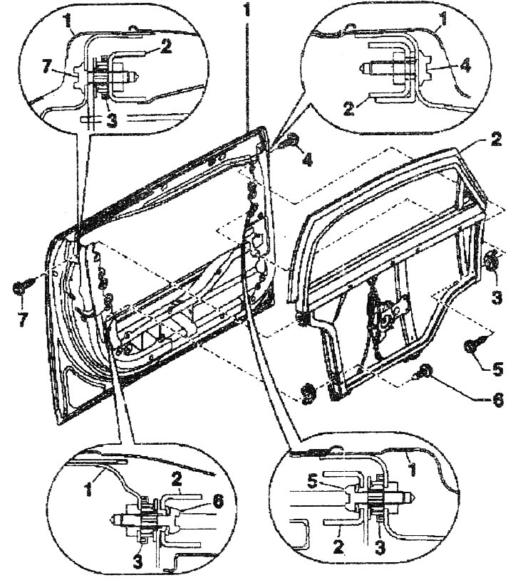
1. Front door. For clarity, the front door/mounting bracket seal is not shown in the illustration. Seal (sealing strips made of polyurethane foam) front door/mounting bracket. Seal (butyl cord "AKL 450 005 05") surfaces between the hinge/safety bar. Close the holes in the safety bar with plugs and sealant.
2. Bracket of built-in door parts. For greater clarity, the seal of the cable guide of the outside mirror in the bracket of built-in door parts is not shown in the figure. Seal (butyl cord "AKL 450 005 05") the outside mirror cable guide in the door integrated parts bracket. To remove, mark the position of the bracket on the door, for example with a thin felt-tip pen. Remove the mounting bracket. Disconnect the electrical wires from the door integrated parts bracket and remove them from the fasteners. Remove the door seal. Loosen the bolts and remove the door integrated parts bracket upwards. Installation: Before installing the bracket, make sure that the adjusting elements are screwed in completely. If necessary, tighten the adjusting elements by hand. Insert the bracket into the door from above. Lightly tighten the bolts. Remove the door seal. Close the door. Align the bracket with the door opening. Lightly tighten the lower bolts. Open the door. Check the gaps. If necessary, adjust the position of the bracket. If the gaps are the desired size, then during installation, tighten the bolts in this sequence to a torque of 30 Nm. Be sure to follow the tightening sequence of the bolts. Seal the outside mirror cable guide with butyl cord "AKL 450 005 05" from the set "Fasteners and gaskets for the mounting plate".
3. Adjusting element. When tightening the bolts, the element is adjusted in length. Before installing the bracket of the built-in door parts, it is necessary to fully tighten the adjusting elements (left hand thread).
4. Bolt Torg, 30 Nm. Observe the tightening sequence of the fastening bolts during installation.
5-7. Bolt Togh, 30 Nm.
Adjusting element
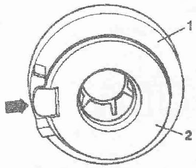
Before installing the bracket of the built-in door parts, it is necessary to screw the threaded bushings "2" of the adjusting element "1" counterclockwise to the end. The locking device "arrow" of the threaded bushing must be located between the stop and the rotation stop.
(Material republished from the website: «AUDIMANUAL.ru»)