



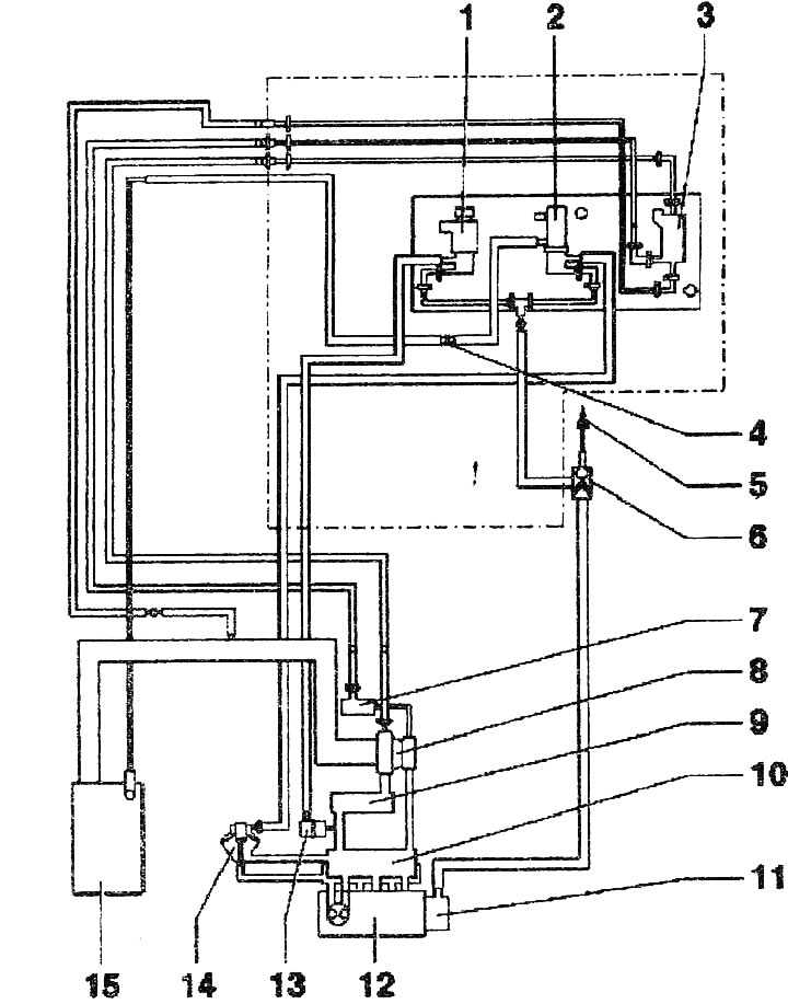
Vacuum hose connection diagram (aMF engines):
1. Intake manifold flap changeover valve "N₂39"
2. EGR valve "N18"
3. Boost pressure limitation solenoid valve "N75"
4. Connecting element
5. To the brake booster
6. Check valve
7. Power pneumatic element for boost pressure regulation
8. Turbocharger
9. Intercooler
10. Intake manifold
I. Tandem fuel and vacuum pump
12. Cylinder head
13. Power vacuum pneumatic element of the intake manifold flap
14. Mechanical EGR valve. Element of the intake manifold fitting, can only be replaced as a set with the intake manifold fitting
15. Air flow meter "G70"
The article is a reprint of material from AUDIMANUAL.ru