
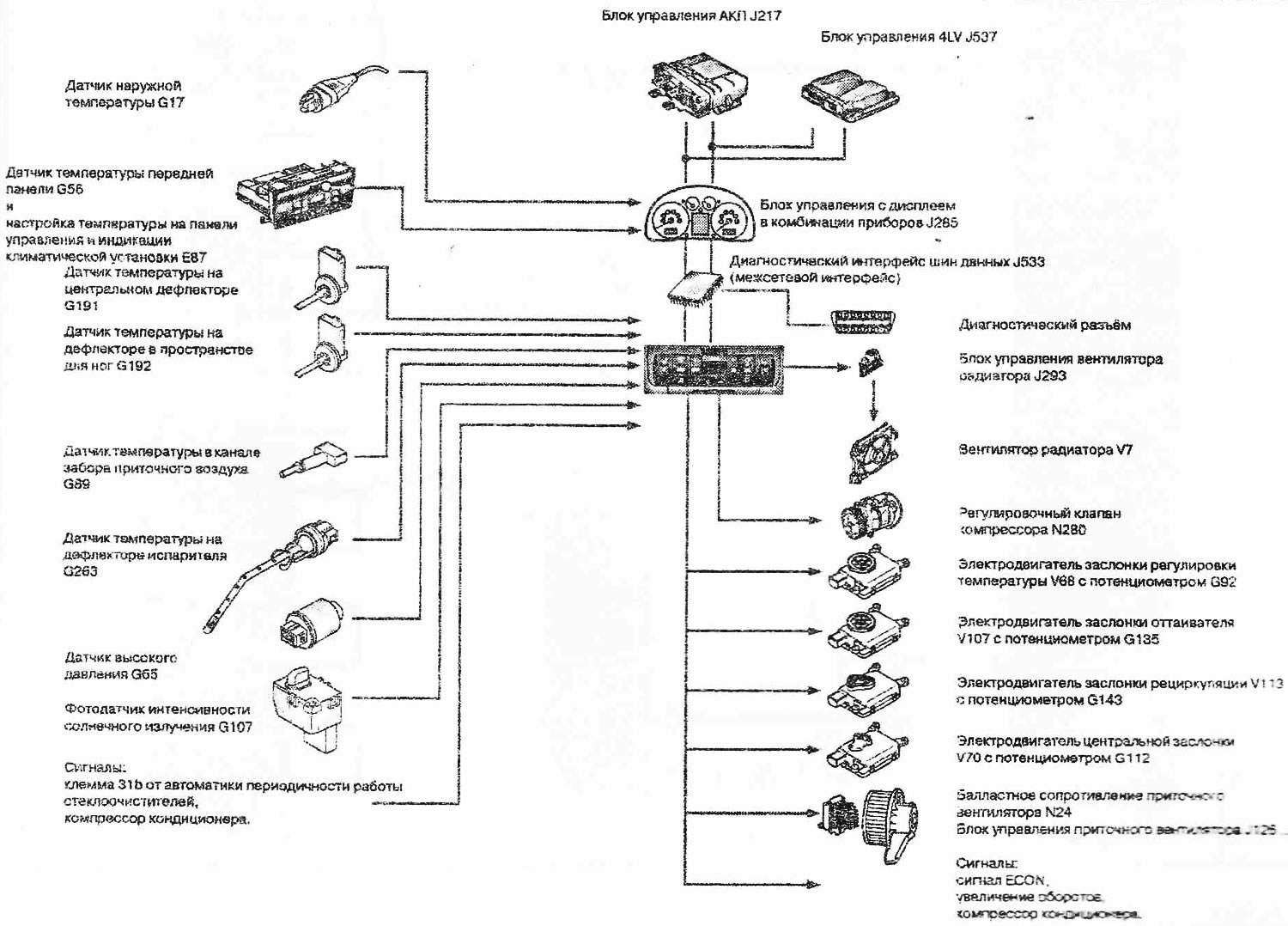
The following parameters are used to regulate the system: temperature on the deflectors (sensors in the air conditioning system); temperature at the evaporator deflector; outside temperature (via CAN from the control unit, in the instrument cluster) from the sensor in the bumper; cabin temperature from the temperature sensor in the air conditioning control panel and the set temperature value; refrigerant circuit pressure; engine specific data (for example, high coolant temperature, acceleration, idle speed).
[The original article is available on the online resource: AudiManual]
Additional heating system diagram (Audi A2)
This article is available at russian, bulgarian, belarusian, ukrainian, serbian, croatian, romanian, polish, slovak, hungarian
Share information:
Previous articles
Audi A2: Heating and air conditioning
Next articles
Similar articles on other Audi car models:
Oil Pressure Warning System Wiring Diagram Audi 80 B3 (1986-1991, petrol)
Pre-heating system Audi 100 C3 (1982-1990, diesel)
Heating, ventilation and air conditioning system Audi A3 Type 8L (1996-2003)
Removal and installation of the exhaust system. Replacement of… Audi A4 B6 (2000-2006)
Electrical diagram of the car heating system Audi A6 C5 (1997-2004)
Pre-heating system for diesel engines Audi A8 D2 (1994-2002)
Parts and units of the fuel system (general diagram) Audi Q5 Type 8R (2008-2017)
Link to this page in different formats
Visitor comments
No comments yet
- General information
- Introduction to the guide
- Maintenance
- Engine 1.4 l (gasoline)
- Engine repair
- Lubrication system
- Cooling system
- Exhaust system
- Engine 1.6 l (gasoline)
- Engine repair
- Lubrication system
- Cooling system
- Exhaust system
- Engine 1.2 l (diesel)
- Engine repair
- Lubrication system
- Cooling system
- Injection and turbocharging
- Engine 1.4 l (diesel)
- Engine repair
- Lubrication system
- Cooling system
- Turbocharging system
- Supply system
- Fuel injection system
- Exhaust system
- Transmission
- Mechanical gearbox 02J
- Mechanical gearbox 02T
- Mechanical gearbox 085 DS
- Chassis
- Car suspension
- Steering
- Brake system
- Body
- Exterior
- Interior
- Seats
- Doors, locks and windows
- Safety system
- Heating and air conditioning
- Electrical equipment
- Power devices
- Equipment and devices
- Wipers and washers
- Lighting and lamps
- Breakers and switches
- Electrical circuits