



Table of contents: Plug connectors of the mobile phone… ↓ Plug connectors for mobile phone… ↓ Built-in Bluetooth Phone Connectors ↓ Connectors of the kit for connecting… ↓ Bluetooth Hands-Free Connectors (CAN) ↓ Bluetooth Hands-Free Connector (MMI)… ↓ Amplifier connectors for mobile… ↓
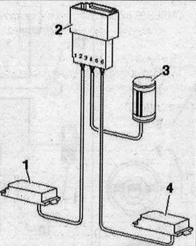
Pinout of the connector 1. Microphone front left "R140" (black); 2. 6-pin connector blue, pins 1-2: front left microphone "R140" (black), pins 3-4: internal microphone "R74" (black), pins 5-6: front right microphone "R141" (blue); 3. Internal microphone "R74" (black); 4. Microphone front right "R141" (blue)
Plug connectors of the mobile phone connection kit (CAN)
Transceiver for telephone "R36"
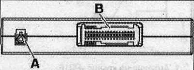
- A - Connector (yellow color) antennas for Bluetooth "R152"
- B - Multi-pin connector, 54-pin (T54a)
Note: Plug contacts not specified are not used.
B - multi-pin connector, 54-pin (T54a)
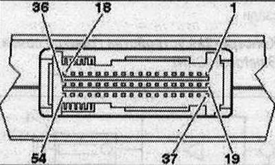
- 1. Terminal 30
- 2. Terminal 31
- 3. Signal to turn on the mobile phone amplifier "R86"
- 8. Low frequency output (+) to the radio "R"
- 9. Low frequency output (-) to the radio "R"
- 10. Terminal 31 (screen ground) (not used)
- 11. Microphone input (+) from the microphone unit in the front roof module "R164" (front left microphone "R140")
- 12. Microphone input (-) from the microphone unit in the front roof module "R164" (front left microphone "R140")
- 16. NF-stumm (mute) (not used)
- 17. CAN-Infotainment High
- 18. CAN-Infotainment Low
- 37. Terminal 30 to telephone holder "R126"
- 39. Terminal 31 to telephone holder "R126"
- 41. Terminal 30 to telephone holder "R126"
- 42. Microphone input (+) to telephone holder "R126"
- 43. Microphone input (-) to telephone holder "R126"
- 44. Terminal 31 (screen ground)
- 45. Low frequency output (+) from the phone holder "R126"
- 46. Low frequency output (-) from the phone holder "R126"
- 47. DIAG signal from the phone holder "R126"
- 49. Ser-Tx (+) to telephone holder "R126"
- 50. Ser-Tx (-) to telephone holder "R126"
- 51. Ser-Rx (+) from telephone holder "R126"
- 52. Ser-Rx (-) from telephone holder "R126"
Plug connectors for mobile phone connection kit (MMI)
Used Electronics Communications 1 "J794"
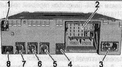
- 1. GSM output from the roof antenna "R216"
- 2. Connector block with four multi-pin connectors
- 3. MOST bus
- 4/7/8 not involved
- 5. Multi-pin connector, 4-pin (T4at) to the front indicator of the used control and indication panel "J685"
- 6. Multi-pin connector, 4-pin (T4ap) to the output for external audio sources "R199"
2 - connection block with four multi-pin connectors
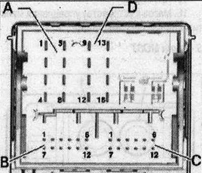
A - Multi-pin connector, 8-pin (T8ah), brown
- 1/4 not involved
- 2. Power supply to the control unit of the multimedia system "E380"
- 3. Wake UP (start) to the control panel of the multimedia system "E380"
- 5. Signal to turn on the mobile phone amplifier "R86"
- 6. Res MU to the control unit of the multimedia system "E380"
- 7. Ring break diagnostic cable
B - multi-pin connector, 12-pin (T12x), blue
- 8. Microphone input (+) from the microphone unit in the front roof module "R164" (front left microphone "R140")
- 9. Microphone input (-) from the microphone unit in the front roof module "R164" (front left microphone "R140")
C - multi-pin connector, 12-pin (T12u), green
All contacts are connected to the output for external audio sources "R199".
- 1. NF-ln mass
- 2. NF-ln on the right
- 3. USB (+5V)
- 4. USB (mass)
- 5. not involved
- 6. Detect
- 7. NF-ln on the left
- 8. NF-ln screen mass
- 9. FBAS cable (+)
- 10. FBAS cable (-)
- 11/12. iPod data
D - Multi-pin connector, 8-pin (T16q), black
- 10. Data from the control panel of the multimedia system "E380"
- 11. Data for the control panel of the multimedia system "E380"
- 12. Terminal 31
- 13. DIAG signal from the phone holder "R126"
- 14. RES VT (stress test) from the control unit of the multimedia system "E380"
- 15. Terminal 30
- 16. Ground to the control unit of the multimedia system "E380"
3 - MOST bus
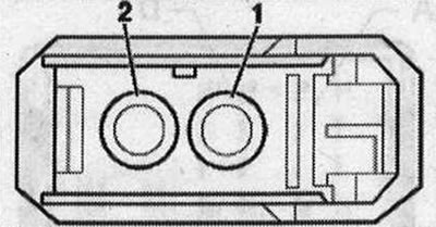
- 1. Login
- 2. Exit
Built-in Bluetooth Phone Connectors
Used Electronics Communications 1 "J794"
- 1. GSM output from the roof antenna "R216"
- 2. Connector block with four multi-pin connectors
- 3. MOST bus
- 4/7/8 not involved
- 5. Multi-pin connector, 4-pin (T4at) to the front indicator of the used control and indication panel "J685"
- 6. Multi-pin connector, 4-pin (T4ap) to the output for external audio sources "B199"
2 - connection block with four multi-pin connectors
A - Multi-pin connector, 8-pin (T8ah), brown
- 1/4/5. not involved
- 2. Power supply to the control unit of the multimedia system "E380"
- 3. Wake UP (start) to the control panel of the multimedia system "E380"
- 6. Res MU to the control unit of the multimedia system "E380"
- 7. Ring break diagnostic cable
B - multi-pin connector, 12-pin (T12x), blue
- 8. Microphone input (+) from the microphone unit in the front roof module "R164" (front left microphone "R140")
- 9. Microphone input (-) from the microphone unit in the front roof module "R164" (front left microphone "R140")
C - multi-pin connector, 12-pin (T12u), green
All contacts are connected to the output for external audio sources "R199".
- 1. NF-ln mass
- 2. NF-ln on the right
- 3. USB (+5V)
- 4. USB (mass)
- 5. not involved
- 6. Detect
- 7. NF-ln on the left
- 8. NF-ln screen mass
- 9. FBAS cable (+)
- 10. FBAS cable (-)
- 11/12. iPod data
D - Multi-pin connector, 8-pin (T16q), black
- 9. Signal to turn on the phone holder "R126"
- 10. Data from the control panel of the multimedia system "E380"
- 11. Data for the control panel of the multimedia system "E380"
- 12. Terminal 31
- 14. RES VT (stress test) from the control unit of the multimedia system "E380"
- 15. Terminal 30
- 16. Ground to the control unit of the multimedia system "E380"
3 - MOST bus
- 1. Login
- 2. Exit
Connectors of the kit for connecting a mobile phone
Multi-pin connector, 18-pin (T18e), black
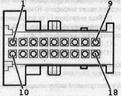
- 1. Terminal 31
- 4. Low frequency mute to radio "B" / communication electronics control unit 1 "J794"
- 7. Low frequency output (-) to the radio "R"
- 9. Microphone input (-) from the microphone unit in the front roof module "R164" (front left microphone "R140")
- 10. Terminal 15
- 11. Terminal 30
- 16. Low frequency output (+) to the radio "Fl"
- 18. Microphone input (+) from the microphone unit in the front roof module "R164" (front left microphone "R140")
Bluetooth Hands-Free Connectors (CAN)
Transceiver for telephone "R36"
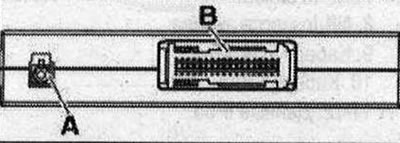
- A - Connector (yellow color) antennas for Bluetooth "R152"
- B - Multi-pin connector, 54-pin (T54a)
B - multi-pin connector, 54-pin (T54a)
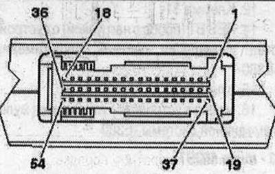
- 1. Terminal 30
- 2. Terminal 31
- 8. Low frequency output (+) to the radio "R"
- 9. Low frequency output (-) to the radio "R"
- 11. Microphone input (+) from the microphone unit in the front roof module "R164" (front left microphone "R140")
- 12. Microphone input (-) from the microphone unit in the front roof module "R164" (front left microphone "R140")
- 17. CAN-Infotainment High
- 18. GAN-Infotainment Low
Bluetooth Hands-Free Connector (MMI) Design
Used Electronics Communications 1 "J794"
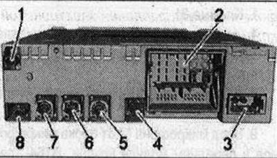
- 1/4/7/8. not involved
- 2. Connector block with four multi-pin connectors
- 3. MOST bus
- 5. Multi-contact connector, 4-pin (T4at) gray to the front indicator device used indication and information "J685"
- 6. Multi-pin connector, 4-pin (T4ap) to the output for external audio sources "RI 99"
2 - connection block with four multi-pin connectors
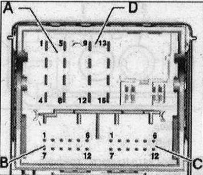
A - Multi-pin connector, 8-pin (T8ah), brown
- 1/4/5. not involved
- 2. Power supply to the control unit of the multimedia system "E380"
- 3. Wake UP (start) to the control panel of the multimedia system "E380"
- 6. Res MU to the control unit of the multimedia system "E380"
- 7. Ring break diagnostic cable
B - multi-pin connector, 12-pin (T12x), blue
- 8. Microphone input (+) from the microphone unit in the front roof module "R164" (front left microphone "R140")
- 9. Microphone input (-) from the microphone unit in the front roof module "R164" (front left microphone "R140")
C - multi-pin connector, 12-pin (T12u), green
All contacts are connected to the output for external audio sources "R199".
- 1. NF-ln mass
- 2. NF-ln on the right
- 3. USB (+5V)
- 4. USB (mass)
- 5. not involved
- 6. Detect
- 7. NF-ln on the left
- 8. NF-ln screen mass
- 9. FBAS cable (+)
- 10. FBAS cable (-)
- 11/12. iPod data
D - multi-pin connector, 8-pin (T16q), black
- 10. Data from the control panel of the multimedia system "E380"
- 11. Data for the control panel of the multimedia system "E380"
- 12. Terminal 31
- 14. RES VT (stress test) from the control unit of the multimedia system "E380"
- 15. Terminal 30
- 16. Ground to the control unit of the multimedia system "E380"
3 - MOST bus
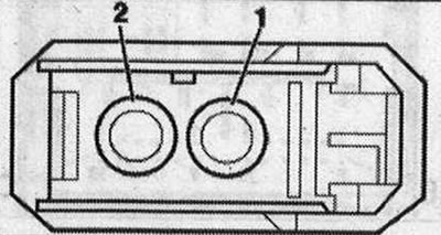
- 1. Login
- 2. Exit
Amplifier connectors for mobile phone "R86"
Mobile phone amplifier "R86"
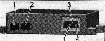
- 1. GSM connector (purple) from the roof antenna "H216"
- 2. Antenna output (purple color) to the phone holder "R126"
- 3. Multi-pin connector, 4-pin (T3ak), black
3 - Multi-pin plug connector, 4-pin (T3ak), black
- 1. Terminal 30
- 2. Terminal 31
- 3. Signal for switching on the telephone transceiver "R36" (CAN)/6/y by the communications electronics 1 "J794" (MMI)
- 4. Control contact (not used)