
Table of contents: Removal ↓ Installation ↓
Removal
Drain the coolant.
Remove the timing belt.
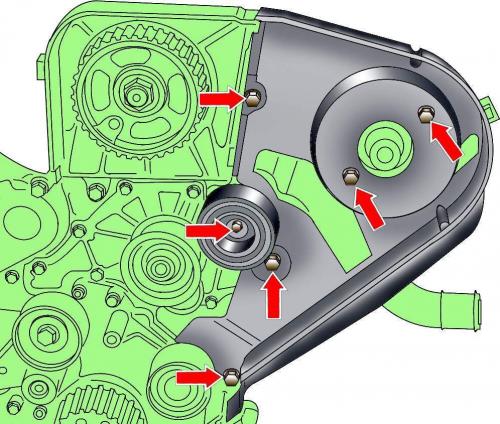
Fig. 3.4–55. Location of guide roller and rear toothed belt cover mounting bolts
Unscrew the guide roller mounting bolt (see Fig. 3.4–55).
Unscrew the bolts and remove the rear timing belt cover (see Fig. 3.4–55).
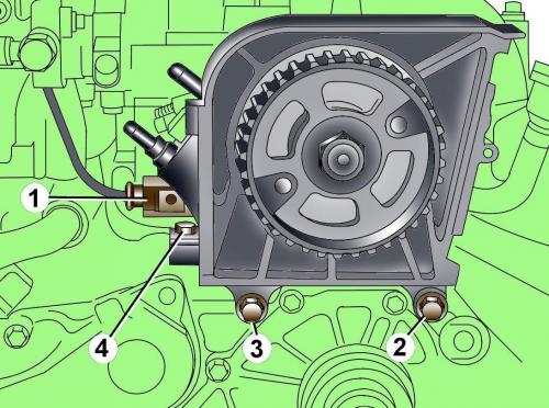
Fig. 3.4–56. Location of the electrical connector (1) and bolts (2, 3, 4) for fastening the high-pressure fuel pump
Disconnect the electrical connector from the high-pressure fuel pump (see Fig. 3.4–56).
Unscrew the mounting bolts and remove the high-pressure fuel pump (see Fig. 3.4–56).
Disconnect the electrical connector from the coolant temperature sensor.
Unscrew the mounting bolts and remove the right and middle pipes of the cooling system.
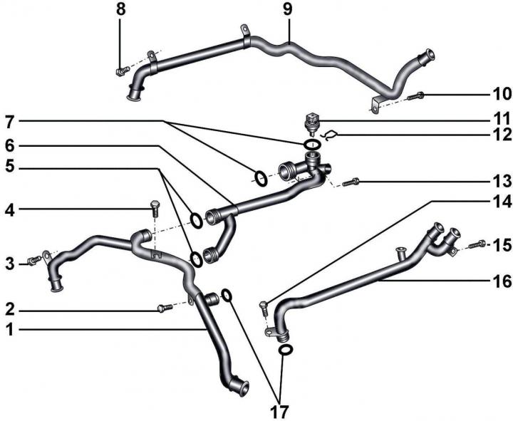
Fig. 7–27. Cooling system pipes of a 3.3 L diesel engine: 1 – front middle pipe of the cooling system; 2, 3 – bolts, 10 Nm; 4 – bolt, 22 Nm; 5 – sealing rings; 6 – right middle pipe; 7 – sealing rings; 8 – bolt, 10 Nm; 9 – rear middle pipe; 10 – bolt, 10 Nm; 11 – coolant temperature sensor; 12 – spring retainer; 13, 14, 15 – bolts, 10 Nm; 16 – left middle pipe; 17 – sealing rings
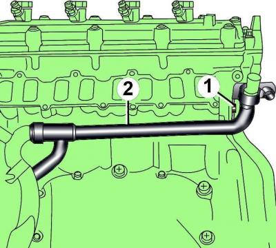
Fig. 7–28. Location of bolt (1) for fastening the middle pipe (2) of the cooling system of a 3.3 l diesel engine
Unscrew the bolt securing the middle pipe of the cooling system and, pulling the pipe back, remove it (Fig. 7–28).
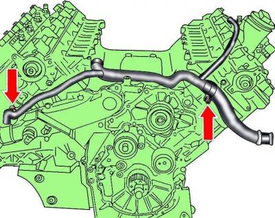
Fig. 7–29. Location of the mounting bolts for the front center pipe of the 3.3L diesel engine cooling system
Loosen the bolts and pull forward to remove the front center coolant pipe (Fig. 7–29).
Installation
Installation is carried out in the reverse order of removal, taking into account the following.
Clean the sealing ring seat before installation.
Install a new sealing ring, after lubricating it with coolant G 012 A8 D.
Fill with coolant.
The original text is available on the website audimanual