
To remove the front bumper
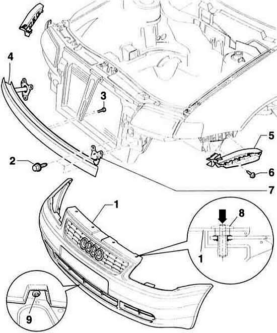
- 1 - bumper trim
- 2 - bolt, 25 Nm
- 3 - hex bolt, 6 Nm
- 4 - bumper
- 5 - guide element
- 6 - self-tapping screw, 1.5 Nm
- 7 - buffer
- 8 - clamp
- 9 - Phillips head screw
Rear bumper elements
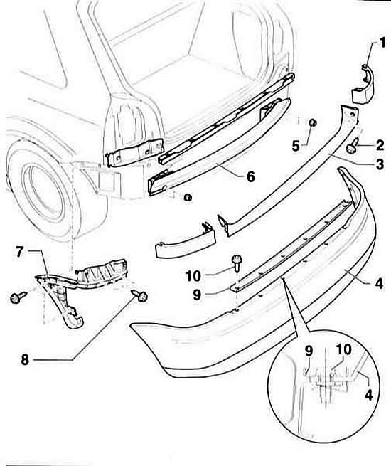
- 1 - visor
- 2 - self-tapping screw
- 3 - lid
- 4 - bumper trim
- 5 - nut, 23 Nm
- 6 - bumper
- 7 - guide element
- 8 - self-tapping screw, 1.5 Nm
- 9 - amplifier
- 10 - self-tapping screw, 1 Nm
Front bumper
Removal
1. Push the insert with a thin pin (arrow on the illustration) on the clamp –8– and remove it.
2. Remove three Torx screws (T25) on the left and right wheel housing.
3. Remove the Phillips head screws –9– from the bottom.
4. Disconnect the bumper trim at the top at the guide element –5–.
5. Detach the bumper trim from the side above the wheel covers and remove it forward from the bumper.
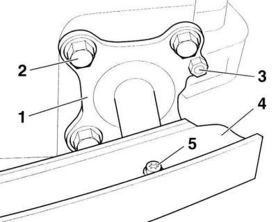
6. Remove the mounting bolts –2– of the support –1– of the bumper –3–.
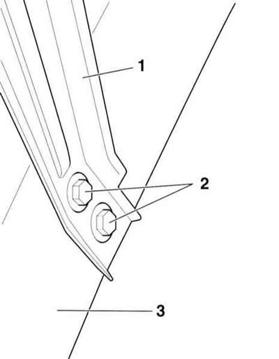
7. Remove the Allen screws –5– on both shock absorbers –1–.
8. Remove the bumper –4– from the shock absorber and remove it forward.
Installation
1. Place the bumper –4– on the shock absorbers –1–.
2. Insert the Allen screws –5– and tighten to 23 Nm.

3. Tighten the mounting bolts –2– of the bumper support to a torque of 6 Nm, refer to the illustration.
4. Install the front trim –1– (refer to illustrationTo remove the front bumper) and adjust it on the side above the wheel covers.
5. Secure the bumper trim to the guide element –5–.
6. Tighten the Phillips head screws from the bottom.
7. Secure the left and right bumper trims to the wheel arch liners with three Torx screws on each side.
8. Insert the clips –8– into the holes at the top of the bumper trim and press the pins (arrow) until they are fully seated in the clip, refer to the detail in the illustration
Rear bumper
Removal
1. Remove the pads –1– on the left and right by unscrewing the screws.
2. Remove cover –3–.
3. Unscrew the screws securing the amplifier –10– and remove the amplifier –9–.
4. Remove 3 screws on the left and right side of the wheel covers.
5. Remove the bumper trim –4– from the top of the guide element –7–.
6. Pry up the bumper trim from the side above the wheel arch liners and remove it to the rear.
7. Unscrew nuts –5– and remove bumper –6–.
Installation
1. Install the bumper in place and secure it with nuts –5–.
2. Adjust the bumper trim –4– from the side above the wheel housings and insert it into the guide element –7– from above.
3. Screw 3 screws into the wheel arch liners on the left and right.
4. Install the amplifier –9– and secure it with self-tapping screws –10–.
5. Replace the lid –3–.
6. Install the pads –1– on the left and right and secure them with self-tapping screws –2–.