
Take it off carpeting in the passenger footwell.
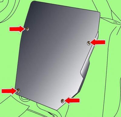
Fig. 18–5. Location of screws securing the electronic unit cover in the passenger footwell
Unscrew the four screws and remove the electronic unit cover (Fig. 18–5).
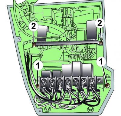
Fig. 18–6. Location of screws (1) for fastening the central electronic unit and guides (2) for the auxiliary relay unit.
Unscrew two screws 1 (Fig. 18–6) and remove the central electronic unit.
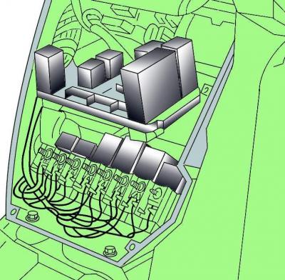
Fig. 18–7. Removing the auxiliary relay block
Using the guides, remove the auxiliary relay block (Fig. 18–7).
Installation is carried out in the reverse order of removal.
(The original text of the material can be found on the website: «AUDImanual»)