
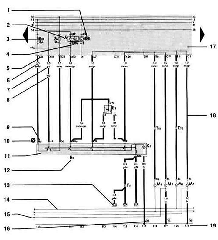
1 - relay number
Indicates the location of the relay on the relay board.
2 - designation of the relay / control device on the relay board
The legend indicates the name of the element.
3 - fuse designation
For example, fuse number 19 (10 A) on the fuse holder.
4 - designation of the plug connection on the relay board
For example, pin 3/49a:
3 pin 3 in place 12 relay board
49a contact 49a on the relay / control device.
5 - designation of the plug connection on the relay board
For example, A13 is multi-pin connector A, pin 13.
6 – wire section, mm2
7 - wire color
8 - embossed number on the white wire
Facilitates identification with a large number of white wires in one bundle.
9 - designation of the connecting terminal
C terminal designation, which can be found on the original part. 10 is the measurement point of the troubleshooting algorithm
The number in the black circle indicates a drawing or an audi troubleshooting algorithm.
11 - designation of the alarm switch
12 - element designation
The legend indicates the name of the element.
13 - indication of the presence of a continuation of the wire
The number in the square indicates the continuation coordinate.
14 - intercom (fine touch)
This connection does not exist as a wire.
15 - indication of the continuation of the inner connection
The letter indicates where the connection continues in the nearest circuit element.
16 - designation of the mass point
The legend indicates the position of the mass point in the vehicle.
17 - relay board with fuse holder
18 - cable
19 - chain coordinate
Visitor comments